ColdFire Test Code (LCD/HDD)
2003-04-07 21:51 by Ian
I haven’t even looked at this stuff in at least 7 months as of 2003.04.07, but I am posting a smattering of the work I did on the MCF5206e. An experienced programmer will note that I am just a beginner with the Coldfire. Unfortunately, most of my time goes towards work and Java…. blech…
The board that I used to write all this stuff was an Arnewsh SBC5206. A very basic M5206 single board computer. When I was a senior in high school, I constructed a simple IDE interface and wrote some code to talk to an LCD and an HDD. The whole saga of that is in the Mp3 Player section. Here is the rest of the code:
Messages.s
Init.s
Equates.s
Some of the output from these programs… Here is the first output of the LCD driver…

...and the beginnings of the IDE driver. You’re seeing results from the DriveID command here. Notice I’ve replaced the circuits on the breadboard with the PCB depicted in the last two images.

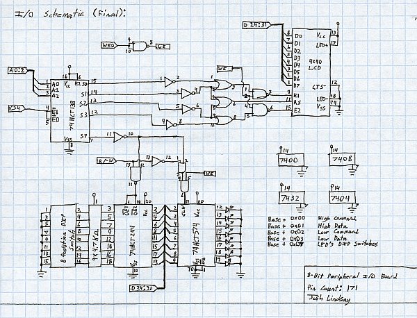
Here is the point-to-point wired pref-board that maps the LCD and an I/O port to a memory block in the 32-bit address space of the ColdFire CPU.

Here is my hand-drawn schematic. In ink. This was drawn in two sittings during my senior year civics class. I hadn’t taken any digital design classes yet, so my optimization is spotty. I could probably eliminate a few of those ICs.
Rather more recently, I got the Micronas MP3 decoder chip working, and so wrote a quick and dirty routine to shift a fragment of an mp3 to the MAS3507D using the Coldfire’s parallel port.
Update 2011.12.06
Including my development notes/journal:
= These are my goals for the player: * Any MPEG1 Layer2/3 audio file playable. * Immaculate audio quality. * Uses a standard ATA hard drive using the FAT32 file system with support for long file names. * Large (4×40) LCD for display. * Voice recognition for hands free operation (This is a project for my car). * User friendly OS so my mother can use it to its fullest potential. * Large (16MB or so) DRAM buffer so I can off-road and still hear the latest Incubus track skip free. * AT Keyboard for rapid hands-on operation. * Playlist support. = These are goals that probably won’t be realized for some time: * Uses an ATAPI CD-ROM using the Joliet file system with support for long file names. * TCP/IP over ethernet. Bare-bones FTP server for updating. * USB interface for updating. * Make either of the above wireless so I can update the player from my PC without running network cable out to my truck. * Rio PMP300 support so I can take my tunes away from the car. Being that I’ve started this log a bit late, much of the research has been completed (I think). So below is a tentative list of the hardware the player will employ along with each parts function. The list is incomplete, but I will expound on it later. * Motorola ColdFire 5206 microprocessor — The CPU * MAS3507D — MP3 decoder * DAC3550A — The DAC * 16MB SIMM, 72 pin, 60 ns — Memory * Motorola 68HC811E2 MCU — Input controller * 4×40 LCD — If you can’t guess this, well…. * AT Keyboard The logic behind the processor choice: This was a difficult decision. After about one week of reading datasheets and looking at development tools and prices, I settled on the ColdFire. I chose this part because of the integrated DRAM controller, I2C unit and the fact that its dev board is only $200. The final reason is what ruled out the Hitachi SH-x series of CPU’s. I don’t have a ton of $$$ to play with. Also, I like the idea that the ColdFire is fast. This will give me the option of adding a TCP/IP stack or maybe even a software decoder later. So wuzzup with the seperate input controller?? I learned assembly and microprocessors with the HC11, and I understand it thoroughly enough to attach several devices to it and have them all work peacfully with each other. It also means that any user input can be handled with one interrupt on the ColdFire. Hopefully, this will make that end of the programming easier. Getting started with a new device isn’t going to be easy. I also like to keep things modular. This way, I can unplug the UI assembly, and replace it with a whole new one if need be. The following things will be under control of the HC11: * Optional AT keyboard * Two rotary encoders – One for song selection, and one for a purpose undefined at this point. * Voice recognition system * Any other input device I feel like adding later. Maybe an IR remote… Well, I am finally tired at 6:10. JMP Josh_Sleep.
Monday 12-25-00 5:12: The beginning I am fighting insomnia, and losing. I decided that the creation of this log was long overdue, so I picked this odd hour to start it. I am designing my own MP3 player because I dislike the idea of using a full-blown PC to accomplish a task so simple as playing music.
Thursday 12-27-00 23:36: Preperation I have settled on the processor, and so I have spent the last two hours sorting thru data sheets and printing the 5XXX ColdFire Programming Manual. Im taking note of how many sheets of text I can run off before my ink cartridge runs dry. So far I am at 240 out of about 650. Needless to say, I might be here all night. I recieved funding today, so I will do my best to start ordering parts tomorrow. Unless something unexpected happens, I should at least get the ColdFire dev board ordered.
This stuff will be used to construct the IDE and LCD glue-logic, and pretty much the entire 8- bit section of the peripheral bus. I spent about 2 hours last night reading the ColdFire’s data sheet, and I decided that the best way to arrange things would be like this: Chip Select 0: 16-Bit EPROM/Flash/Whatever Chip Select 1: Not sure if the DRAM needs a CS line. I don’t think it does, but I’ll keep this open anyways. Chip Select 2: IDE Chip Select 3: All the 8-Bit stuff. This includes the LCD, the input controller, and several groups of DIP switchs and LEDs. Not sure about the input controller however. I might connect it to one of the ColdFire’s UARTs. Suggestions anyone? Now I’m waiting on the LCD so I can start prototyping (is that a word?) the 8-bit section. At least I can test that with a parallel port. I will try and draw up schematix of my idea later.
Monday 12-31-00 4:07: Waiting…. Well, as I should have foreseen, Mr. Murphy made an appearance and something unexpected happened. I tried to order the ColdFire board on 12-28-00 (I swear I did) and I was greeted by a kind message: “I’m sorry, but our offices are closed due to inclimate weather.” The next day they were closed as well, and New Years Eve and all… But there was progress! I ordered the 4×40 LCD from www.eio.com, and tonight- well, last night- I went to Fry’s Electronics and bought the following: * Large solderless bread-board * 40 pin header (IDE Connecter) * Miscellaneous IC’s, DIP switchs, small LEDs
Monday 01-08-01 21:25 Good news and bad news… The devboard the I was going to order has been discontinued and the next one on my list is almost twice as much. Consequently, it took some time to get the cash to order it. I got it ordered today, but the big problem is it will take 4-6 weeks to get here. The updates might be few and far between until then. There is good news tho! I began breadboarding the parts of the circuit that is external to the devboard. This includes the IDE stuff, LCD, etc…
Tuesday 01-16-01 2:00 Waiting… I got all the manuals printed out. Hey, I’m doing all I can while waiting for that processor. I was looking around at other people’s designs, and I saw a chip I had never seen before: The STA013. Not only is this chip cheaper, but the pin-out is simplicity itself (28-pin SM-dip). More research is required. I want to get this board as small as is practical, so any part I can get in SMD form will be my first choice. I have never soldered onto a SM board, nor have I ever made one. Any suggestions/help/warnings? Oh yeah! I got the LCD a few days ago and it is currently wired up and working.
Hard Reset DRAM Size: 16M Copyright 1995-1996 Motorola, Inc. All Rights Reserved. ColdFire MCF5206 EVS Debugger v1.1 (Dec 16 1996 10:19:41) Enter ‘help’ for help. dBUG> Time to get coding! Sh*t Dogg, I LOVE Fridays!! I took a pic.
Friday 01-26-01 16:54 Yippy!!! It got here! Really fast! I am happy! I dropped everything, ran to my room, fired it up and was greeted by this message from Hyper Terminal:
Saturday 01-27-01 12:36 Progress! Ten minuets after I wrote my previous entry, I fell asleep. I didn’t get back up until about 18:00. I immediately rose to go seek nourishment, and before long stumbled onto a box of pizza. After that, I spent most of the night setting up my workbench to accommodate the new board, acquiring a DOS terminal emulator, and setting up my development PC. Then I slacked off and played PlanetFall for a few hours :). But anyways, after some reading and screwing around in DBug, I hand assembled this statement: ADDQ.L #0×01,D0 This preforms a quick addition of a value between 1 and 8, to the given register (D0). But that instruction assembles into this: 0×5280 I used DBug’s mm (Memory Modify) command to write this word into address $10000. Then after executing it, I checked D0, and it was 1!!! Yey!! Please don’t laugh at me… I’m tired, so that concludes this night’s progress.
Saturday 02-04-01 1:08 Progress^2! Leaps and bounds of advances today! After a whole week of hair pulling sessions with the board, I got sick of moving floppies across my room and working on two different computers. I ended up bringing my PSU, the board, and my 4×20 terminal to my desk next to my main system. I got a freeware TFTP server from 3Com’s site and eliminated the annoying terminal file transfers. This sped things up tremendously. After about 7 hours without leaving my chair, I got the UART fully initialized, interrupts working as I wanted, bi-directional communication with my terminal (on UART1), and I played around a bit with the TRAP #15 thing. I set it up so that whenever I hit escape on the terminal attached to UART1, my program stops and relinquishes control to dBug, and therefore, the main terminal. Took more pix. As a side note, I found a binary Linux image for my board at www.mortonbay.com. I took a break to install that. The output is considerably garbled (designed for a 24×80 TRM), but its there. I took a pic of that too. I’m late. It’s tired. I am go.
Tuesday 02-06-01 18:43 I’m having a wonderful time… Spent Sunday driving around the Phoenix area trying to hunt down a female 2×40 header. I finally found one at a remote Fry’s Electronics store. I probably spent $5 worth of fuel to obtain $1.80 in connectors. Ick. I wish these sort-of things were more common. What this means is that I can start grafting my own hardware to the board. The next targeted problem is learning to speak ATA. Stuff is moving along at a reasonable pace. Things are slightly slowed because I have to work now. But today I got the timer working and generating interrupts at a consistent rate. I found the simple little error that was screwing things up for a whole week. Only the 22 most- significant bits are valid address bits. Several of the bits are unused, but one bit – the least-significant – is the ‘valid’ bit. If this bit is not set, all internal modules that bank off of the MBAR will be inaccessible (Hence, my physical bus errors). RTFM Josh. Oh well, it worx now. I am trying to clean up my code so it looks presentable enough for others to read. Once I get it clean, I will post it. As a side note, migrating as I am from an 8-bit architecture to a 32-bit one, I’ve noticed that not only does the code get messy to look at, but the compiled result in huge! I’ve written 116 lines of assembly, and the s-record is 936 bytes already! That would have been a little less than half of my available space on my old HC811.
Wednesday 02-07-01 18:10 This whole project is going very well Mom let me ditch school today on the grounds that I needed to restore my “mental health”, so I caught up on much needed sleep, went to work etc… I got home and decided to wire up my breadboard. As I have posted earlier, the eight-bit segment of this thing is working already. So after a little set back (I screwed up the R/W line’s polarity), the bread board and the coldfire are now getting their chat on. I anticipate that with the timer working and all, I will be sending text to the LCD by the end of the night. But not before I take a small break.
Thursday 02-08-01 00:02 This whole project is going very well (II) Not as far as I hoped to be. I got the memory locations for the LCD mapped out, sending individual characters, etc, but I don’t know how to preform indexed addressing yet. This means I can’t easily send a string of characters. Work continues….
Wednesday 02-14-01 19:29 First draft of LCD driver is working I spent the whole day at school trying to determine the best way to write this. Here is the format I decided on: Each character/command to be sent to the LCD takes up one word of memory. The first byte is a marker that determines where the next byte will go. I did it this way because the LCD I am using is a 4×40 with two HD44780 type Marker | Destination controllers. The thing is basically two separate modules in one ———-|—————————- assembly sharing all the connections except enable lines. What 00 | High frame command this means to the software is not much more than some careful 01 | High frame data planning on my part. So here is what the initialization 02 | Low frame command string and basic greeting message look like: 03 | Low frame data Setup&Message: 04 | Both frame command DC.B 0×04,0×38,0×04,0×38,0×04,0×38,0×04,0×38,0×04,0×0C 05 | Both frame data DC.B 1,72,1,101,1,108,1,111,1,32,1,119,1,111,1,114,1,108 06 | End of data DC.B 1,100,1,33,6 07 | Delay The above three lines are the data required to set up the LCD and print out “Hello World!”. 0×04 is the destination marker, and 0×38 is a command. Note that the marker 0×04 causes this command to be sent to both controllers at once. The addition of the Dual_Comm and Dual_Data routines causes the display to fully initialize a full 200mS sooner, and it saves 1.64mS per screen clear.
Sunday 02-18-01 22:05 Got sick of cluttered breadboard I’ve spent the whole week trying to figure out some way to extract a -IOR signal from the coldfire’s pins. I found one person who is trying the same thing I am, and I am not encouraged. I know it is possible because Arnewsh successfully implemented an ISA bus which utilizes the -IOR signal I require. I will find a way… Anyways, I did do this: I got tired of messing around with the rats nest of wire that was hiding the surface of my breadboard, so I took the whole thing apart. I only rebuilt the IDE section. All the 8-bit stuff got crammed onto a piece of prefboard. When I say crammed, I really mean it. I point wired the whole thing. Seven ICs, a DIP switch, eight LEDs, some connectors, and a SIP resistor pack all got squeezed into a 60cm� space. I took pix of both sides of the board. I am awfully proud of how that thing turned out. It took me damn near 8 hours to build, and another 2 to figure out that the -WE signal wasn’t being inverted like it should have been. Aren’t you glad you wern’t the guy who had to solder this?
Monday 02-19-01 00:07 WOOHOO!!!!! I know I am making this entry only a few hours after the last one, but… WOOHOO!! I got -IOR! Yey!! I read the drive ID! I’m so happy, I took a SS! No some real work can begin!
Friday 02-23-01 23:06 I’m Scared I am afraid to start writing the ATA driver. It is a very intimidating task. I did get a bit of work done however. I can read all 256 words from the DriveID command, and can also extract bits of info out of that and compile it all into a screen refresh. I also got the binary to ASCII converter working. Now I can feed the sub a register, and it will generate eight ASCII characters to represent the number in hex. I am waiting on a larger hard drive because my current one is very old (1993), and doesn’t support LBA. Moreover, its too small (340MB) to support a FAT32 file system. I should have a 1.6GB drive within the week tho, so I won’t be delayed too long. Oh yeah, I’m having this weird problem with my LCD. It seems if the start of the timer interrupt handler is at a certain address, the LCD output becomes garbled. Severely. The characters are correct, but when they end up on the LCD, its as if the program has added 2 to the ASCII value of half of the characters. So e(101) becomes g(103). Strange huh?
Sunday 02-25-01 14:44 It’s coming along (slowly) Took a pic of and have updated source for DriveID. Its working better now. I am going to go seek consumables.
Saturday 03-10-01 14:45 [Stalled] I am having problems. The hard drive I am using refuses to get a sector. Not only that, but every drive I attach to this thing seems to not like being put in a PC after I try to talk to it. I can still use the drive, but I must set its parameters in BIOS myself. I think I know why this happened however. My code for reading the status and error registers was reading the high byte of the IDE bus. It should be reading the low byte. Consequently, my status and error register readings were all messed up. At least things will be a little clearer from now on out. With this new change, I also decided to redo the code that gets the data from the hard drive. Instead of doing a loop based on an absolute value (256 loops for 256 words per sector), I just check the status register after every read. This will allow the same sub to be called for read operations of any length.
Sunday 03-11-01 17:57 Bad hard drive! I found a nasty little bug in my hardware. My IDE addressing scheme wasn’t allowing two of the registers to be read. Fixed that up. Thats about it. I worked all night last night and much of today on this problem: I can’t read a sector for reasons unknown to me. Thanks to the fix I made yesterday, I can now get accurate status of the drive. Here is what happens… I load the drive/head, cylinder, sector and sector count registers with the desired values: Next I give the command (0×20) to the drive to read the requested Cyl-High = 0×00 sectors with retry. The result is an aborted command error. I don’t Cyl-low = 0×00 know what happened. I’ve read the sector count, sector, cyl-high, Drive/Head = 0xE0 cyl-low, and drive/head registers to be sure that the correct data is Sector Count = 0×01 getting sent to the correct locations, and everything looks alright… Sector = 0×00 Drive/head register is set this way: Addressing mode = LBA, Drive 0 selected, Upper four bits of LBA set to 0×00. I tried running the initialize drive parameters command and using CHS, but then I get ID not found errors. Grrr…
Sunday 03-18-01 18:05 Good hard drive! With a bit of software tweaking and experimentation, I FINALLY read sectors off of the hard drive. I was ignoring the DRVRDY bit in the status register before. If anyone who is new to implementing ATA/ATAPI is reading this, learn from this mistake: If you ignore DRVRDY, you will nix your hard drive, I promise. I toasted a 1.6GB Western Digital doing this. The symptoms were these: * Slow to negate BSY in the status register. * Because of the above, if the damaged hard drive is ever used in a PC again, it will probably not autodetect in BIOS until about 30 seconds after its power up. * Funky behavior while reading sectors. The 1.6 exhibited odd behavior when I was trying to read sectors from it. Only after using a new hard drive was I able to determine what went wrong. CHECK DRVRDY BEFORE YOU WRITE!!
00047E00: 58 EB 4D 90 57 53 4E 49 2E 34 00 31 08 02 00 20 X.M.WSNI.4.1… Any ‘puter gurus out there should spot this. The bytes have been reversed on a word-by-word basis. It should look like this: 00047E00: EB 58 90 4D 53 57 49 4E 34 2E 31 00 02 08 20 00 .X.MSWIN4.1…. EB 58 90 is Intel hex for a JMP instruction. This jumps to the OS bootstrap code. “MSWIN4.1” is just a text string and is basically meaningless. At first I thought that all this was due to the differing ways that Intel and Motorola CPU architectures store data. x86 CPUs are “little endian” wheras most Motorola CPU’s are “big endian”. Say you want to store the 32-bit hex number 0xAB1245CD at address 0×40000. If you were using an Intel CPU, your memory would look like this: 00040000: CD 45 12 AB However, a Motorola CPU would do this: 00040000: AB 12 45 CD The IDE interface has a 16-bit data path, and thus, this is a consideration. Seeing as how I’m using a big endian CPU to talk to a device that was developed for use primarily on a little endian architecture (ATA), I thought I just didn’t consider this while I was wiring up the IDE interface to the data lines (Could that be the problem in the 03-10-01 entry???). Then I reallized that my DriveID command was giving me data in the proper order! WTF?!? After a little reading on the internet, I found that this endian-ness problem applies to files and stuff stored on the hard drive as well as the interface. Ooops. I guess I found my problem. I must write a function to switch the two halves of the word, but not tonight. I have school tomorrow, and I have a long day of sleeping in class ahead of me.
Monday 03-19-01 0:49 Number problems… Brace yourself, this is going to be a long and very technical entry. I have encountered a problem that has me scratching my head in complete and total confusion. Remember that sector I read several hours ago? It was sector 1 (MBR) of a linux partition. I know very little about how linux works, so I didn’t see the problem that had surfaced. Earlier tonight I did “fdisk /mbr” on the drive and made a bootable FAT32 partition. Linux is one thing, but DOS is another thing entirely. Unlike linux, I know what a FAT MBR should look like. This is a hex/ASCII dump of the first 16 bytes of the MBR:End_Flip: MOVE.L #Temp_Word1,A2 MOVE.L #Temp_Word2,A3 MOVE.B (A2)+,(A3)+ MOVE.B (A2),(A3) MOVE.L #Temp_Word1,A2 MOVE.B (A3),(A2)+ MOVE.B -(A3),(A2) MOVE.W Temp_Word1,D0 RTS This is the data before and after: Before: 00047E00: 58EB 4D90 5753 4E49 2E34 0031 0802 0020 X.M.WSNI.4.1… 00047E10: 0002 0000 F800 0000 003F 0080 003F 0000 …......?...?.. 00047E20: 49C1 004C 130E 0000 0000 0000 0002 0000 I..L…......... 00047E30: 0001 0006 0000 0000 0000 0000 0000 0000 …............. 00047E40: 0080 5E29 F43B 3207 3035 2030 2020 2020 ..^).;2.05 0 00047E50: 2020 4146 3354 2032 2020 33FA 8EC9 BCD1 AF3T 2 3….. 00047E60: 7BF8 C18E 78BD C500 0076 561E 5516 22BF {...x….vV.U.”. 00047E70: 8905 007E 4E89 B102 FC0B A4F3 D98E 00BD …~N…........ And after: 00047E00: EB58 904D 5357 494E 342E 3100 0208 2000 .X.MSWIN4.1… . 00047E10: 0200 0000 00F8 0000 3F00 8000 3F00 0000 ….....?...?... 00047E20: C149 4C00 0E13 0000 0000 0000 0200 0000 .IL….......... 00047E30: 0100 0600 0000 0000 0000 0000 0000 0000 …............. 00047E40: 8000 295E 3BF4 0732 3530 3020 2020 2020 ..)^;..2500 00047E50: 2020 4641 5433 3220 2020 FA33 C98E D1BC FAT32 .3…. 00047E60: F87B 8EC1 BD78 00C5 7600 1E56 1655 BF22 .{...x..v..V.U.” 00047E70: 0589 7E00 894E 02B1 0BFC F3A4 8ED9 BD00 ..~..N….......
Wednesday 03-21-01 17:43 Tiny, but very significant… As explained in the previous entry, I must reverse the endian-ness of any information I grab off of the hard drive. Here is my endian reversal code (Temp_Word1 contains word to be flipped):I ordered the STA013, DAC, several capacitors, crystals, and other assorted parts. I got the surface mount parts soldered to the DIP adapters. I have a new problem. One that might loom over me for some months to come. The ColdFire has no SPI system, only a syncronous UART. The bit order is reversed, and the UART insists on inserting start and stop bits into the data stream. The STA013 doesn’t like this. Over the past month, I have been toying with several ideas to extract these troublesome bits, and each idea involves a large chip count. In-and-of itself this is not a problem, but I know nothing about PLD’s or FPGA’s. Time to learn…. I REALLY don’t want to use two GPIO pins from the ColdFire to feed the MP3’s to the decoder for reasons that ought to be obvious (High CPU usage, no interrupts, slow stream, etc…). If I could use the UART to handle all of the dirty work of shifting the bits out, generating the interrupts, and holding several bytes in a queue, this whole thing will run much more smoothly. I have even tried building my own custom UART to SPI converter from discrete logic and latches. How’s that for desperate?
Thursday 04-25-01 0:39 Lots has happened, but little has changed… Apologies for the long absence, but alot has been going on. My final year of high school is rapidly winding down and so my priorities have shifted. I am going back to Memphis, TN for the entire summer, and I will be living on my own for the first time. I’ve been working as much as I can to raise enough money to sustain myself for six months.Pin | Device addressed ——|———————————— 0 | LCD high data 1 | LCD high command 2 | LCD low data 3 | LCD low command 4 | Latch/DIP-switch 5 | ATA chip select 0 6 | ATA chip select 1 7 | MCU used for SPI
Tuesday 05-29-01 15:48 Absent again Again I have been absent, but this time, more has happened. I moved back to Memphis on 05-17-01. So I’ve spent the two weeks since then getting settled, finding work, catching up (Not coding). The two weeks prior to that, the following occurred: – I wired up the STA013, DAC, and support components. – Wrote the code to initialize the I2C module. Wrote the ISR for it, and entered all of the values in the config file into my program. The Coldfire can now send the STA013 its config data. – Fried the STA013. I think. I am not getting acknowledge bits from it, and there is no conclusive sign of life. Why can’t there be a 5 volt version??? – Discovered a MAJOR hardware/software glitch. I have been using separate chip select pins to address the IDE devices and the 8-bit I/O. CS5 was the IDE, but before my program runs and initializes it, Debug leaves it alone as an address line. What all this means is that before my program runs, the IDE interface is being addressed at random. This is why some drives cause the Coldfire to lock up, die completely, or otherwise act silly. I think I fixed it. I am using CS4 exclusively to address all external hardware. This also brings us to….. – The SPI issue. I have decided that the best way to do things is to use a small Microcontroller with an SPI to handle things. This means the use of an external interrupt pin and a new chip (maybe a PIC), but thats no big deal right now. The MCU will be grafted onto the existing 8-bit section using one of the vacant demultiplexor pins. Here is the breakdown:
Sunday 11-24-02 18:45 Woohoo!!!!! It breathes!!! It lives!!! It plays Nirvana!!! After days of fighting this thing, the MP3 decoding hardware plays the distorted, but clearly recognizable, recording of Nirvana – Verse Chorus Verse. It’s about f*cking time!!! I am so happy! This thing has actually been decoding MP3’s for the last two weeks, but the DAC circuit was all messed up, so I couldn’t hear anything. This means several things: * A chance to test my code. This was sorely needed. It is very reassuring to know that, after reading datasheets for a few years, I wrote correct, fast, and stable code right from the get go. Currently, I am simply bit-banging the parallel port pins of my development PC. No very smooth. In fact, I can only play 96Kbps files and below with no skips. This is ok tho. I will move the SPI duties over to the HC11 in due time.
Wednesday 12-25-02 19:57 Woohoo part deux. Problems… I implemented a ring-buffer with 160 bytes of the HC11’s memory and set up the SPI in interrupt driven mode. I used the /~IRQ pin as the new data strobe from the PC. No good. All the components of this program work fine apart, but when combined together… yuck. It would appear that my little 2MHz HC11 isn’t quick enough to handle the massive amount of data being crammed into it. Without DMA capability, the real-time data shuffling can’t happen. This leads us to the Coldfire. It has no SPI, but I plan on implementing this in the CPLD if need be. Well, now that I know that the decoder and DAC circuitry work ok, I can focus on getting the data there in a timely manner. The DAC needs to be committed to its own PCB, however. The noise and distortion that the other digital circuitry introduces is not pretty sounding. I wired the GPIO port on the Coldfire to the serial lines and flow control of the MAS, wrote some quick code, copied an MP3 into memory, and GO 10000. Instant Papa Roach. Oh cool! I just got a good idea! I’m gonna go now to profile how much CPU time is being used to emulate an SPI...
Previous: The hammer tester
Next: DTMF Logger