The hammer tester
2002-09-23 23:56 by Ian
My first experience working as an independent contract engineer was for my dad at age 19. His customer wanted him to build a machine to test hammer handles under both abuse and cyclic fatigue scenarios. He's a mechanical/materials guy, and handled the design of the machine itself (although I did some of the machining). But he hates computers like poison, and subcontracted the control and measurement systems out to me.
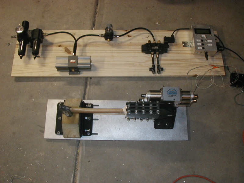
After about three weeks, this is what we would up delivering. Here is the entire machine. Visible is the striker assembly (bottom of frame), and support board we mounted parts to for delivery. It was expected that the customer would remount the contents of the support board onto surface(s) of his choice. The support board contains (from left to right) air filters and lubricator, a pressure doubler, pressure regulator, bi-directional flow valve (with neutral position and an actuation solenoid, and finally on the far right, the controller that I built to run the whole thing.
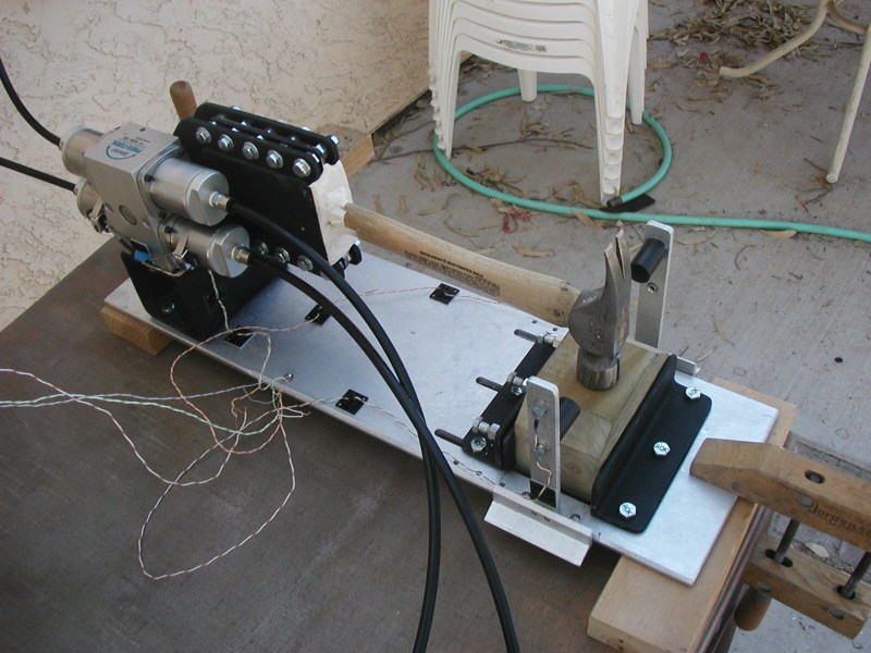
Here is the striker assembly. This piece has a 90-degree pneumatic actuator rated for 250psi, and capable of providing the required acceleration for the mass of the heaviest framing hammers. Dad deemed the bearings and shaft of the actuator to be able to withstand the cycles/beating we were going to subject it to.
There is a hole and clamp pattern for mounting interchangable strike targets. Here, the striker is configured with the plain 4x4 that I used for power calibration. The customer agreed to take responsibility for the safe shielding of this machine as he saw appropriate to its installation context.
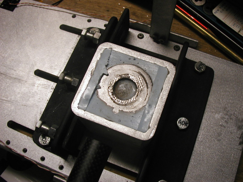
Here is one of the demo targets we made. It is just silicone of a known durometer cast into aluminum channel, with an embedded steel washer for load spreading. You can see the brutal strike scarring in the high-hardness steel from our demo framing hammer.
The incoming shop air is expected to be wet, and at least 125psi. It is regulated down to 120psi, dried, lubricated, and boosted to 240psi before being regulated back down to 225psi. This is a common design pattern in fluid mechanics of all sorts (including electrical). You boost above where you need to be to give yourself a constant regulated output pressure, even under load. Then you regulate as lightly as you can at the final fluid delivery stage.
The valve is basically a pneumatic H-bridge. When unpowered, it returns to its neutral (all paths blocked) condition via internal springs. Flow through the valve is related to the direction of the solenoid's drive current. Reverse the current and you reverse the air flow in the slave attachment.
Strike power is modulated by the amount of time that the valve is allowed to remain in the open position. When it closes, some of its acquired momentum is reconverted to pressure in the volumetricly-decreasing cylinder pair (which was formerly open to atmosphere). This effect was compensated for by a priori calcaulation, and hard-coded into a linearized scale-factor that the user could then understand in terms of a percentage, with 0% resulting in a gentle traversal of the arc until it came to rest on the target with a faint tap.
The acceptance criteria was that the machine needed to be able to completely drive a 16-penny nail into a pine 4x4 in a single blow. Our machine met that criteria at 80% power (with some power left-over, judging by the marks). I set this as the default strength to simulate a capable man. I put safety features in the firmware to allow the default power setting to be pushed into the super-human range. The customer loved that demo. he had planned out a strike target for abuse testing that would shatter a maple hammer handle in a few cycles.
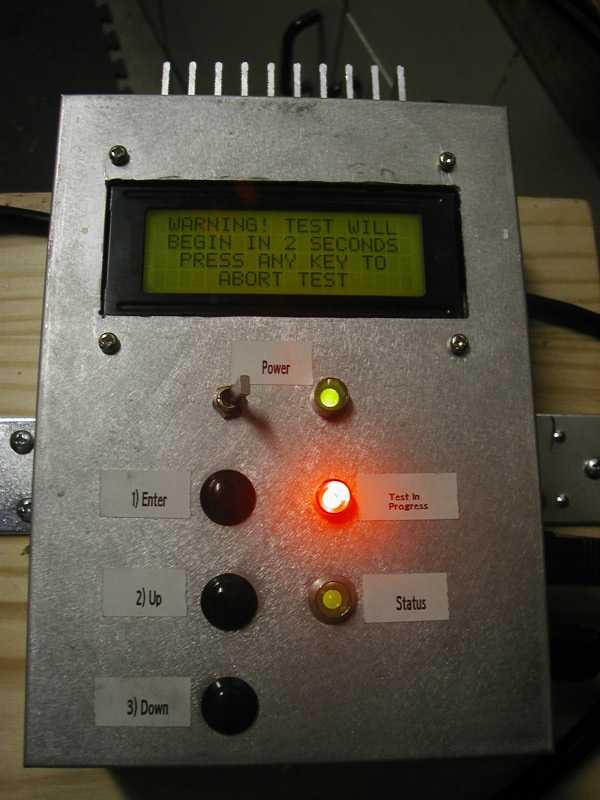
The controller was (of course) an HC11E2. The UI is a common LCD character display, and three-button input. A menu system allows the user to do cycle testing, single-strikes, adjust testing parameters, and display test logs (which were recorded to non-volatile memory). The hardware knowledge-loop was closed by a pair of hall sensors in the actuator, and a pair of IR break-sensors in the target frame stanchions. The velocity of each strike is measured, and a total strike energy calculated based on an optional head-weight input by the man running the test.
Handle breaks are inferred by either (a failure of the velocity sensors to detect an expected passage of the hammer head), or (an excessive spike in measured strike velocity between cycles). Breakage of the light path outside of a strike will also abort the strike (and the test, with a special error). I demonstrated this last safety measure with my own hand.
Here is a picture of the user interface prior to starting the test. That bright red light is pulsing at 5Hz and is plainly visible under any lighting conditions.
The entire program could be used via a serial port, which would take commands and issue results for each strike, and a full report on test conclusion. This was well more than the customer asked for, but I had the code already, and space left over in the HC11's 2KiB of program EEPROM. Even after implementing the floating-point functions for the physics calculations.
It took me about three days to build the controller's hardware, and about two weeks to write and debug the firmware.
Previous: A capacitance meter built from discrete ICs
Next: ColdFire Test Code (LCD/HDD)