The Woose Tracker
2019-08-08 10:59 by Ian
This project is a wearable child's toy for team games. I have two children that are young enough to start drawing treasure maps and playing sophisticated games of hide-and-seek. And they both watch cartoons that have characters with wearable computers. So I embarked on a quick project to build something that was meant to be used for fun.
This post will update as the build progresses.
Features and capabilities
- The basic Heltec WiFi LoRa 32 v2 board.
- An IP67 speaker, driven by an amplifier and one of the the ESP32's DAC channels.
- An eye-safe red laser pointer (because kids love lasers).
- A bright RGB LED
- An analog light sensor to store ambient calibration points to inform display and LED brightness choices.
- A vibrator motor for tactile feedback.
- GPS with a dedicated compass sensor.
- 2500mAH battery driving two switching regulators at 3.3v each. Both regulators are voltage-stopped to protect the battery.
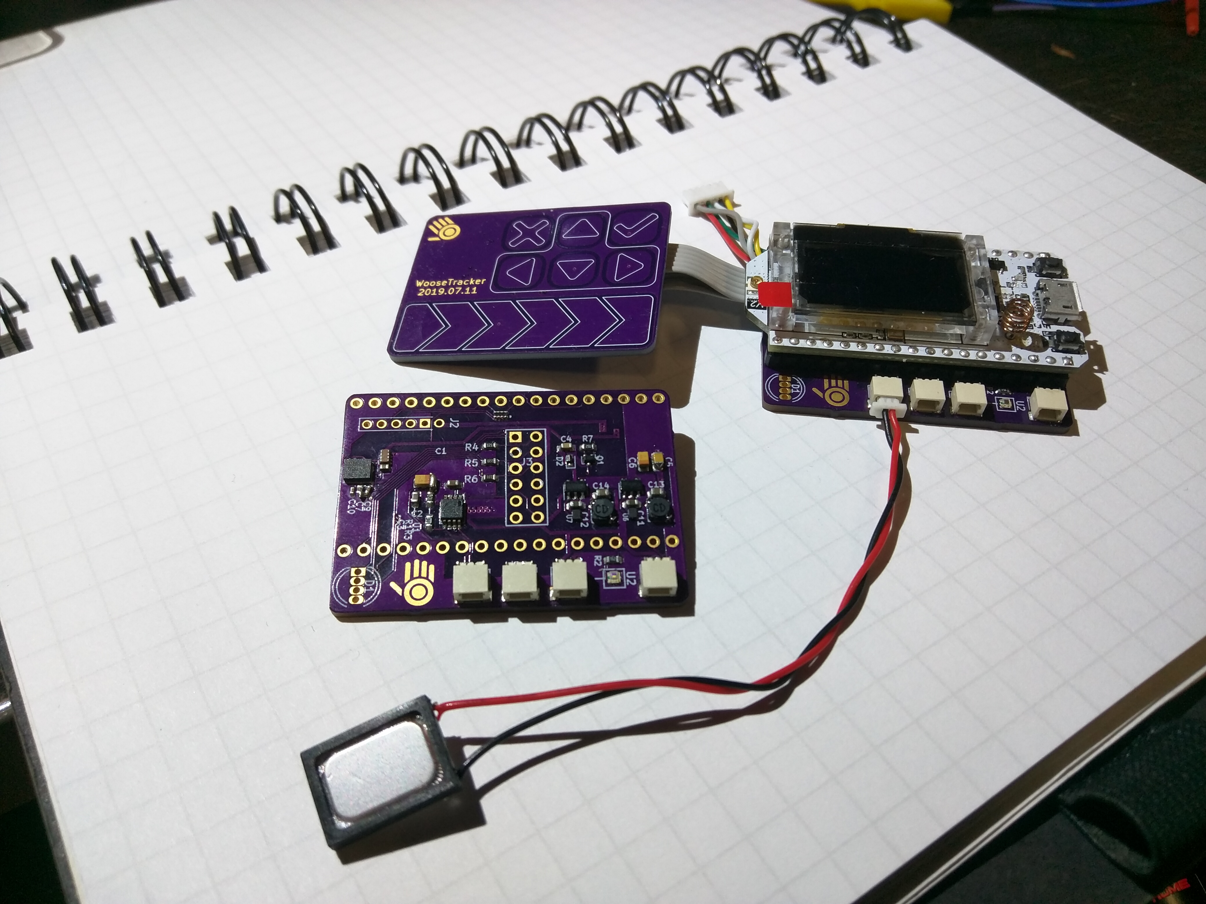
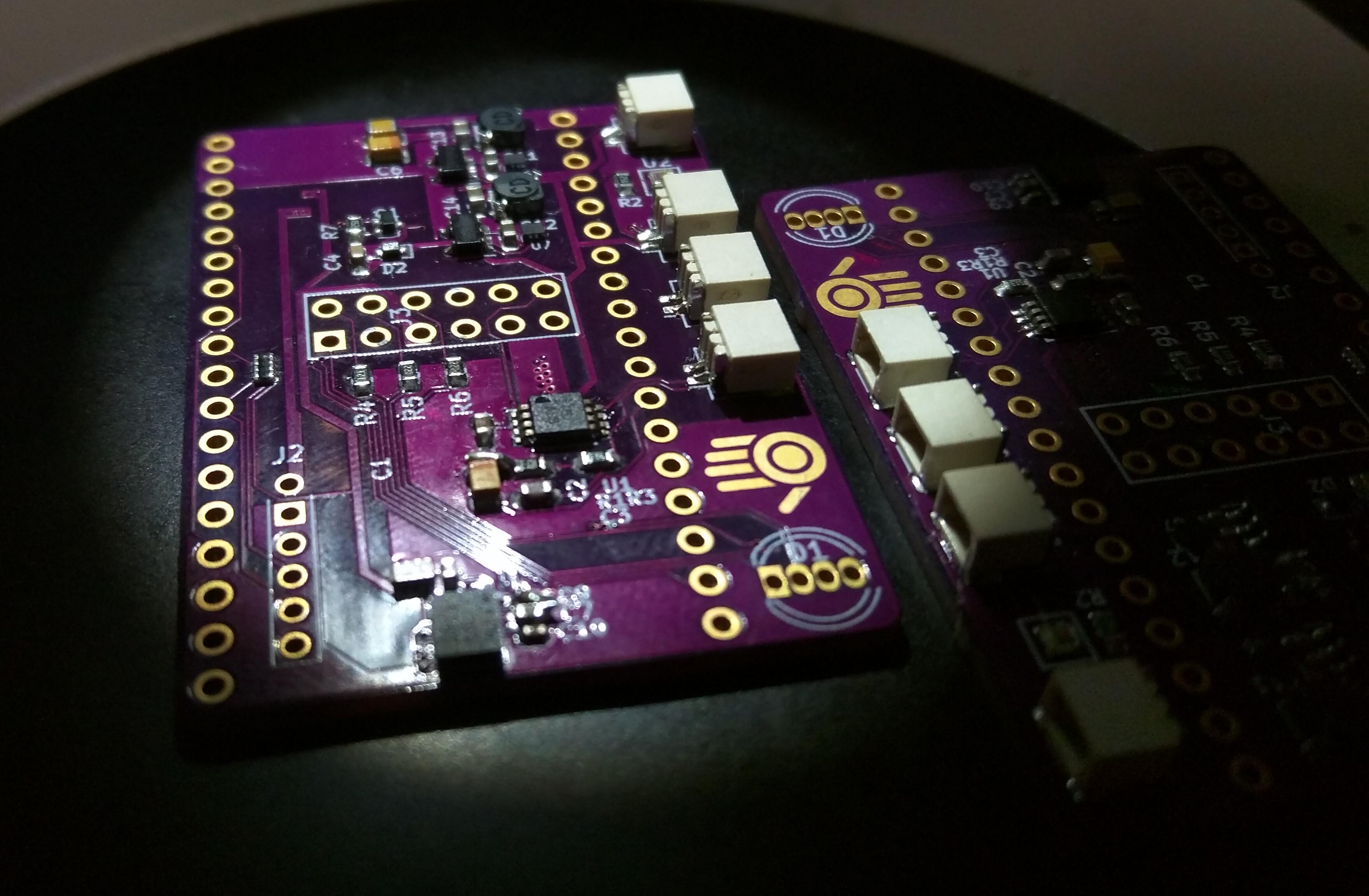
Current state of assembly:
"Start at the end and work back."
--- Neil Armstrong
Shown with only the speaker and touch board connected.
Preparation for attachment:
I considered rolling de novo hardware, and if I replicate the design more than 6 more times, I will. But for a quick-turn, the Heltec module was too convenient. So despite the smaller, slower, monochrome display, and higher profile, I used it for the first two.
The peak current draw will exceed the stock regulator's capacity. And it's presence conflicts with my battery-management strategy. So I removed it, and will power the Heltech board from the base plate. It is the (still intact) SOT5 part in this shot through the microscope.
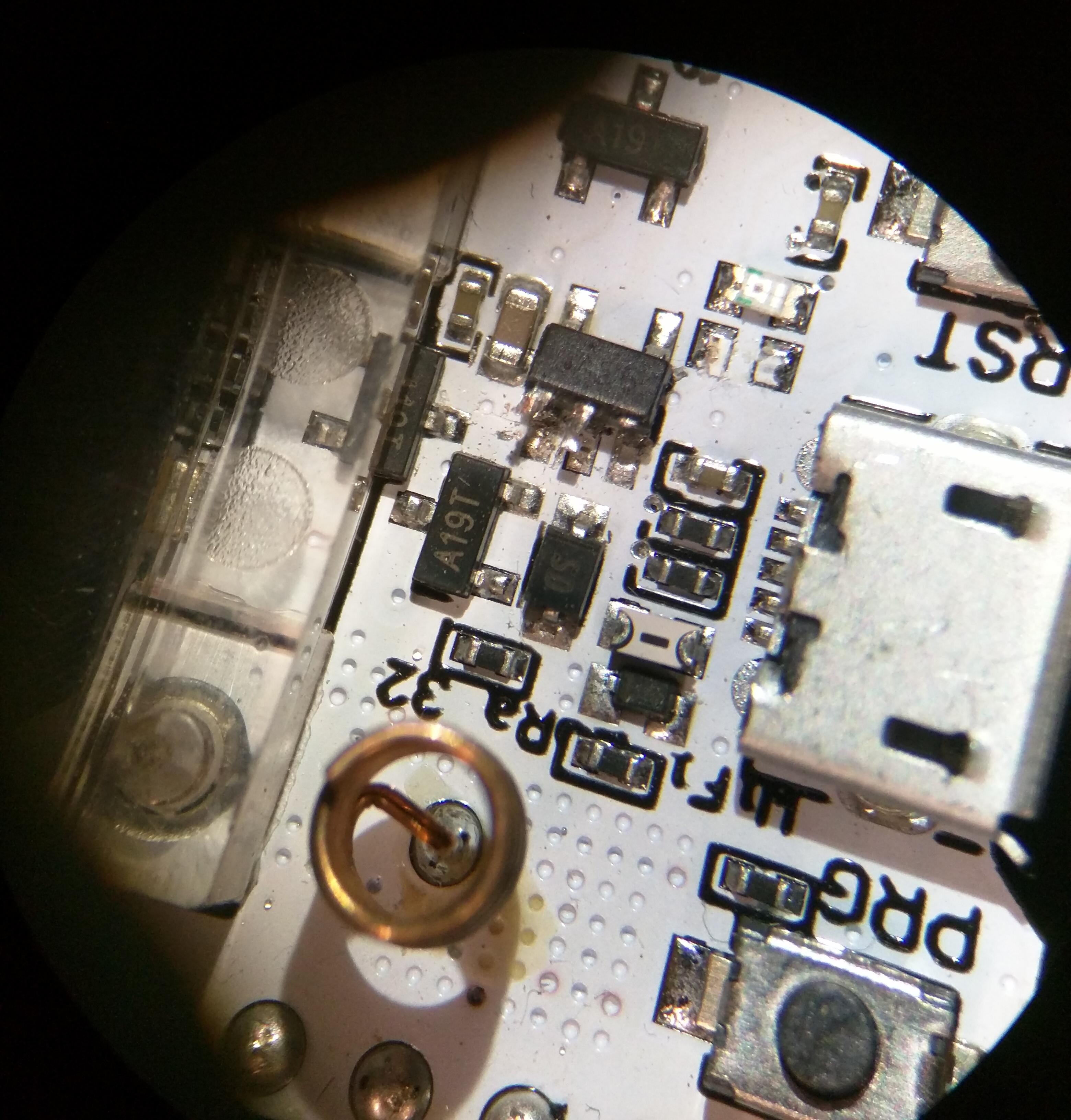
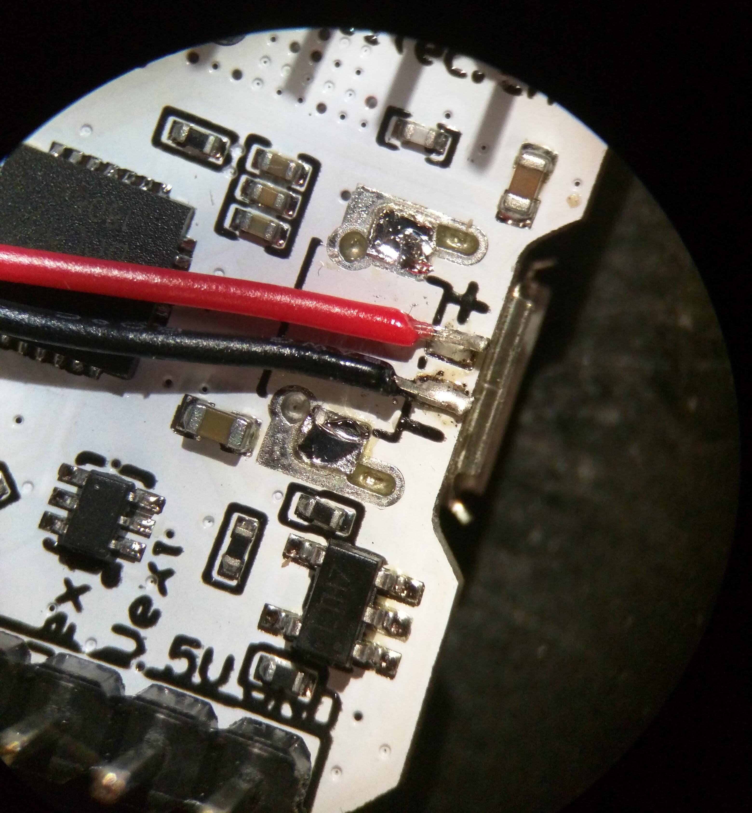
But I still want to use the onboard battery charger to keep costs down. And there is no pin on the board that carries the unobstructed battery voltage. And the connector that comes stock on the board is in a bad orientation for my mounting plan. So I removed the connector and jumpered it to the base plate. If a next revision happens, this will be a non-issue. So I accept the hack with the understanding that I only need to do it twice for my test units.
I needed to test a specific regulator for another project, and I wanted a split-rail power design as part of the battery management strategy. If not for this, I would have copy-pasta'd my PowerPlant module onto the base plate, rather than roll a fresh version of it. Any next revision will use the larger and slightly more expensive PowerPlant for the sake of deeper firmware involvement in the battery state.
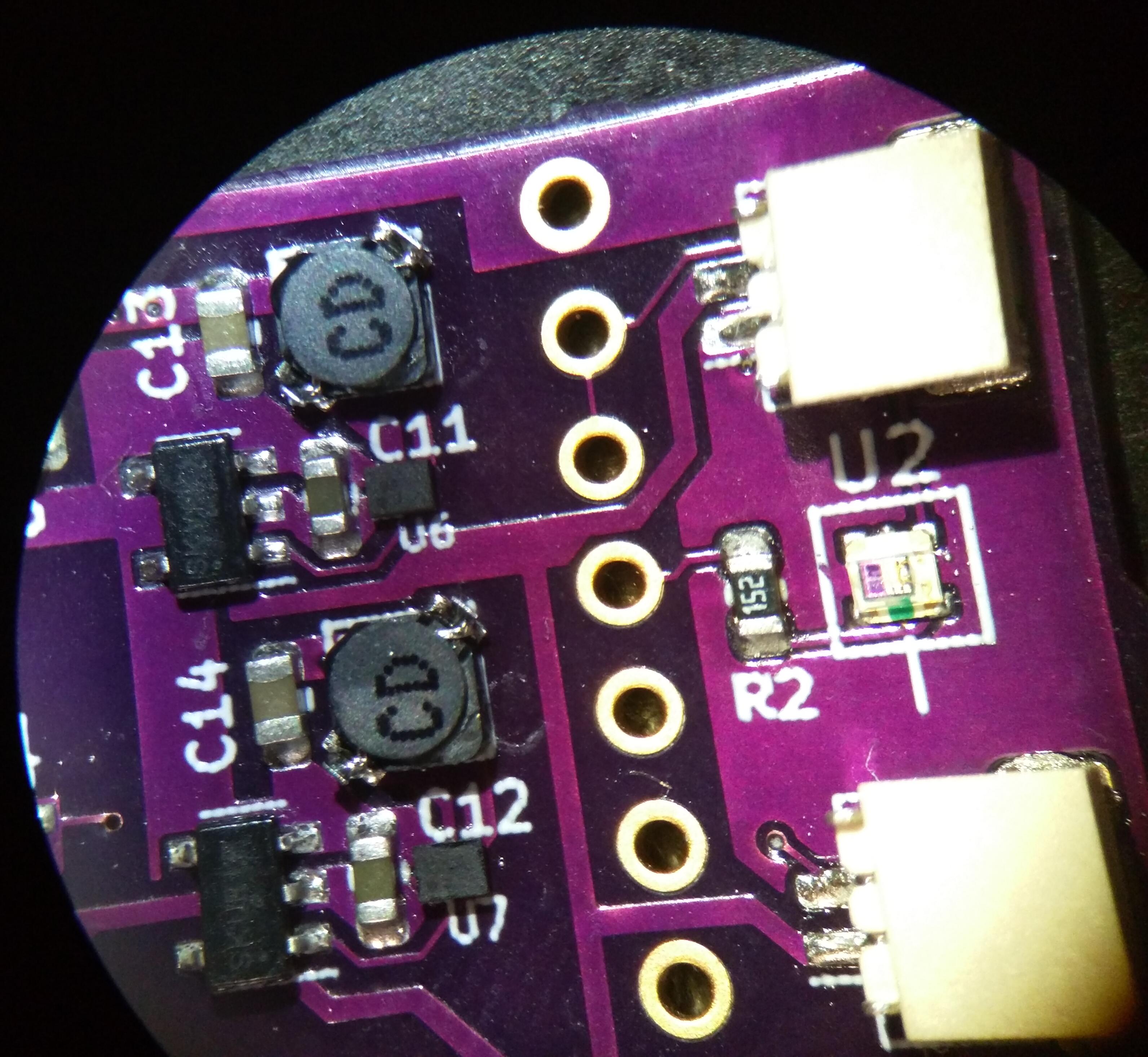
Here is a close-up of the regulators on the base plate. The much larger SOT5 packages are the voltage monitors for each regulator. They are at a 100mV spread to hard-cut power to any non-critical peripherals and give the firmware a warning when it's battery is critical.
Hooking it all together...The hardest problem for mechanical work will be created or solved by how I design this board. It contains the regulators, an IMU, audio amplifier, some scattered transistors and passives, and connectors for the laser, battery, GPS, LED, and speaker.
Mechanicals.... I've got three radio antennas in three separate bands, a touch sensor that needs to be on the top surface, a display that is anchored in a co-planar relationship to the board, and it has to sustain the abuse that a toddler will inflict upon it. I haven't solved all this yet, but will post renders once I do.
Firmware and hardware validation
The touch board is one of the recent breakouts I built in July. I have finished the Manuvr driver for it. It has conditional build-time support for upload of arbitrary configuration, and burning that configuration to the chip's NVM. This was required for this project, since some of the pins are used as inputs, and the default configuration from Semtech has all GPIO pins defined as outputs. Since the signals are all low-speed, I could have probably solved this danger with series resistors, but I didn't. Thus, the default configuration has to be installed in the touch board's NVM before the board is attached to the WooseTracker or hardware damage will occur.
The regulators, laser, audio subsystem, jolt, and touch board all work. Everything else is yet untested.
I made a small mistake on the audio amp's input side passives (unconnected net). Solved by a fat blob of solder. Fixed in schematic and will be present in next rev.
Previous: Recent breakout boards
Next: Viam Sonus 2.0