Hardware CI Arrangement
2025-06-22 16:54 by Ian
When someone asks me how long I've been doing embedded work, I should just send them this picture.

This is just since 2015, and so doesn't have all the kits going back to my Adapt-11, and the Arenwsh SBC5206. Nor does it include any of the more modern Linux SBCs (RasPi, Pine, etc). Nor does it include anything I've done for employers. Nor machines pressed into service. These are only the eval kits, and the eval kits I've built for myself. This forms my embedded "library" for the past 10-years. And now I have to choose what ends up under test.
BLACKHAND
TODO: Fill out.
At the center of everything, there is a Raspi5 running instance runners for both GitHub Actions, and my local GitLab installation, as well as the tools required by the test programs....
- Mosquitto
- A local Linux program for exercising GPIO control of some of the rigs features.
- Functioning as a platform target in its own right for Linux programs that are built on C3P.
- Logic analyzer host software.
BLACKHAND also hosts an observation camera for the sake of giving feedback on devices that otherwise have no better option. LCD/OLED displays, LED behaviors, etc.
TODO: pics, or it didn't happen.
Attached hardware
3-axis pipeline test board:
This PCB holds a variety of 3-axis sensors. Magnetometers, gyroscopes, and accelerometers. Apart from serving to test their drivers, I also do integration testing of C3P's TripleAxisPipe classes using these for inputs.

All common signals to the board are broken out on the bottom with a nice label. Signals that are not shared are on the top via the right-angle female IDC connector.

WiFi containment:
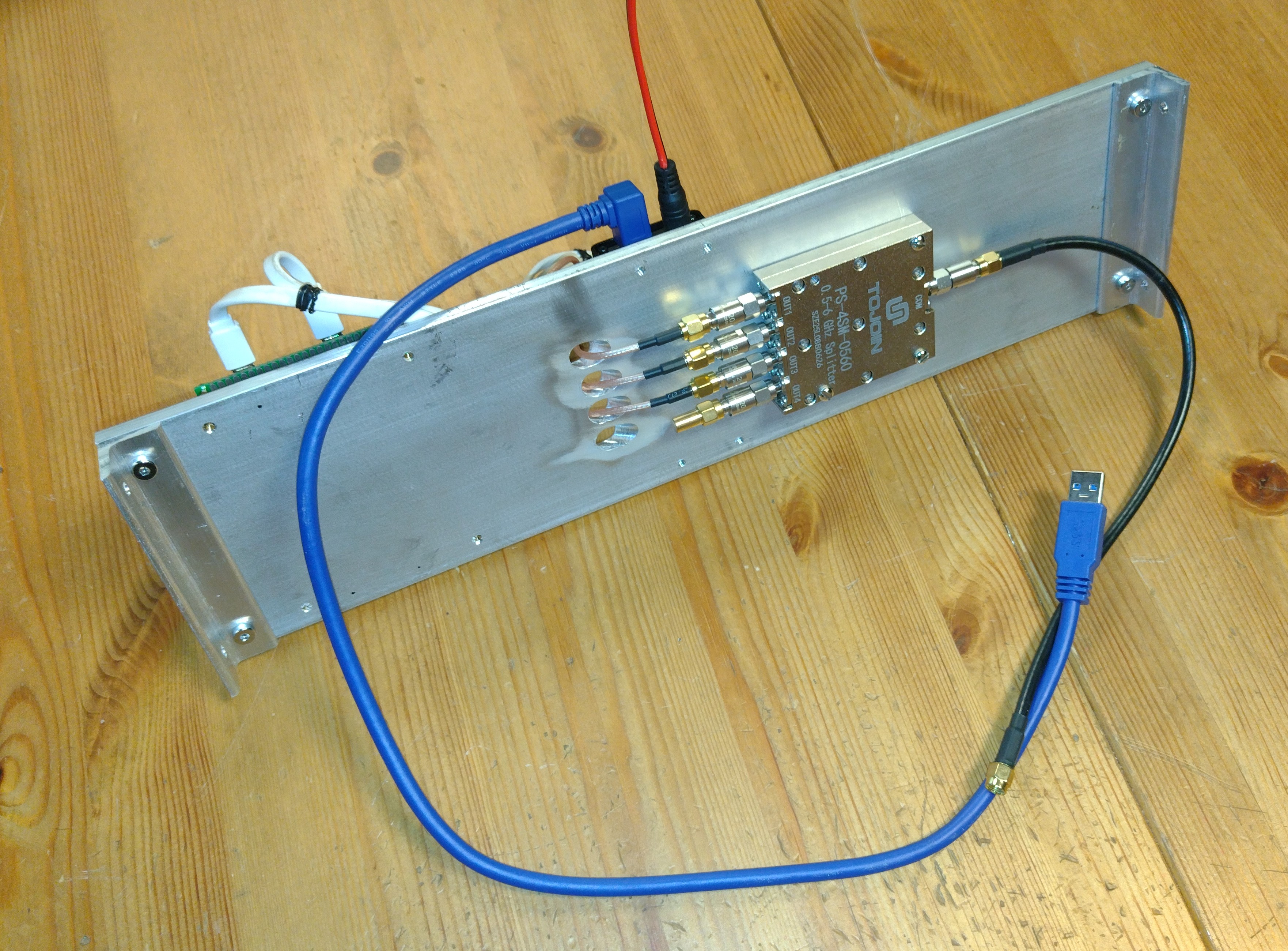
This is a finished plate that holds an isolated 2.4GHz ISM radio environment.
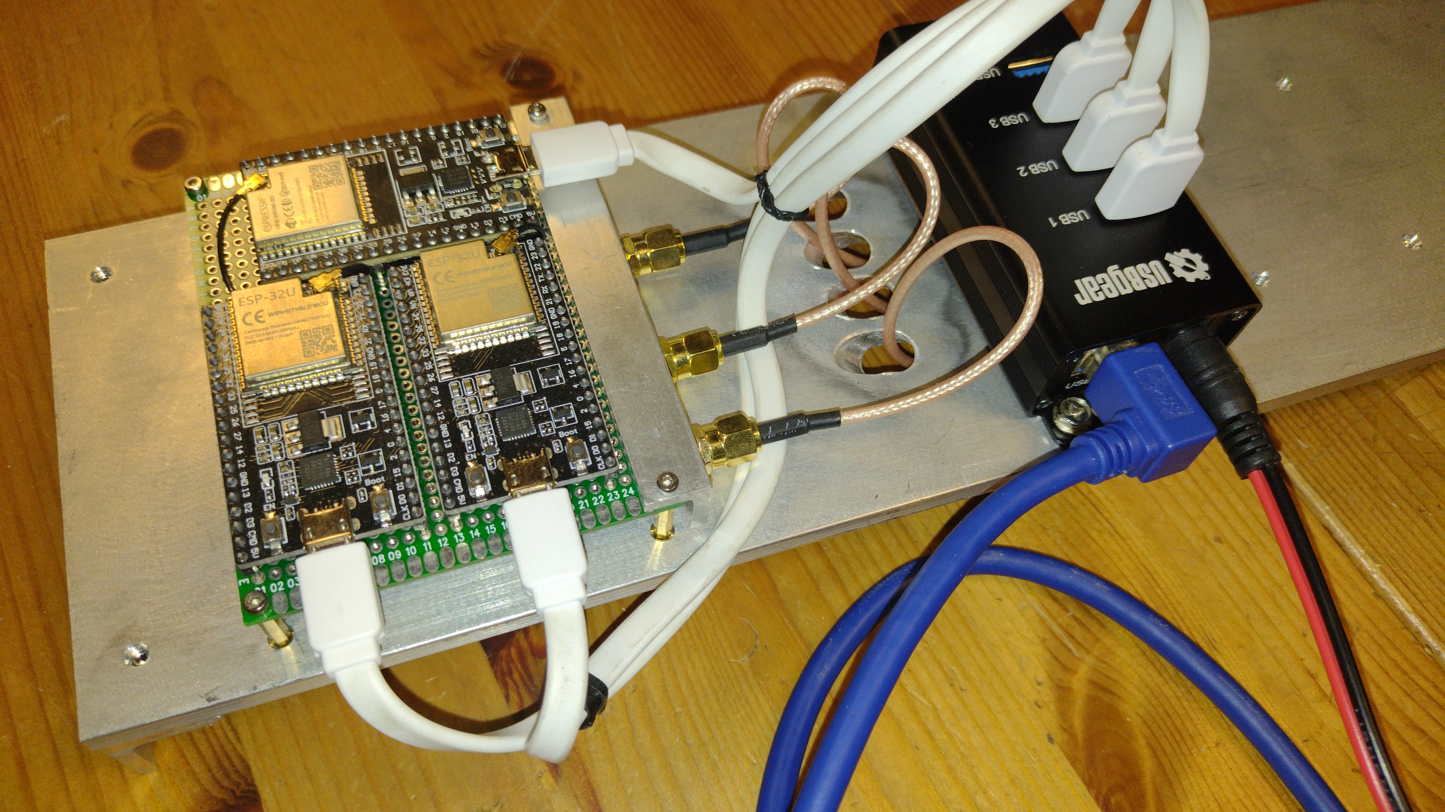
The devices under test (DUT's) are three WROOM32u modules with their RF pigtails and USB cables neatly tucked and broken out onto an SMA bracket. Also visible is the powered USB hub to present them to the CI runner via a single USB cable with no power burden (which may be high with all three modules screaming into their shared radio prison.
The ISM-band environment is contained in this RF splitter and the cables connecting to it. Not only does this prevent my running CI jobs from annoying other devices on the band, but helps them run more reliably because the converse is also true. I'm fed up with re-running CI/CD jobs because someone decided to start using the microwave oven during the last run.
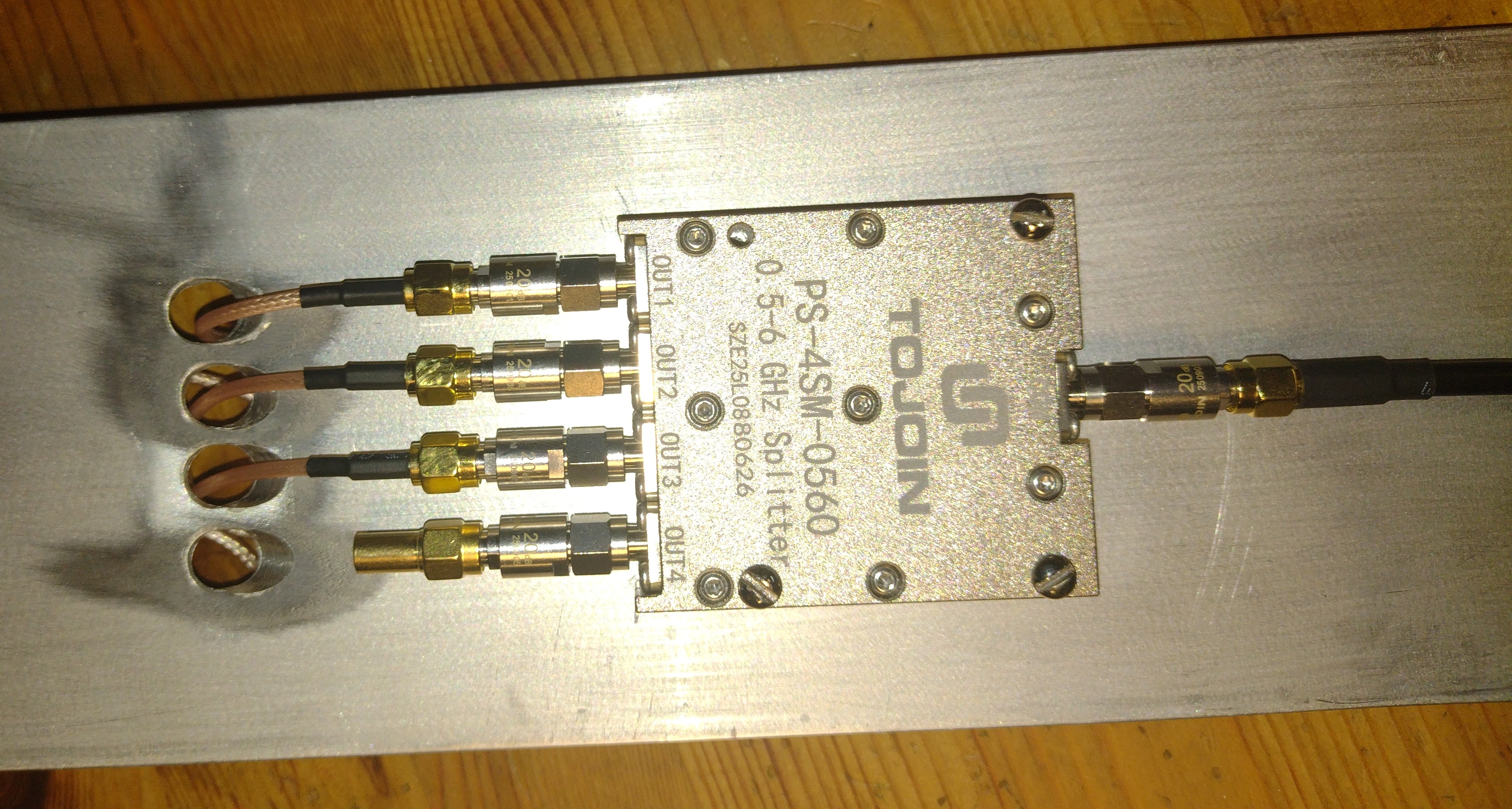
About all that screaming... Because I am directly connecting radios that are intended to communicate over (possibly) many kilometers of noisy free-space, we don't want to blow out everyone's RX channels. Each port on the RF splitter is guarded by a -20dBm attenuator. Without these, it would be like having three guys with megaphones crammed into a phone booth. Because this is a test runner, I will assume that at least one of those guys will start talking with the megaphone volume set to maximum. So I need to do the radio equivalent of filling their megaphones with expanding spray foam.
After the -7dBm insertion losses into the splitter, all of this assures a minimum attenuation of -47dBm between any two endpoints, which I think should near-enough represent the low-to-mid range of mutual audibility. Since there is practically no noise in their shared "airspace", it should be good enough to test happy-path communication more-or-less reliably.
There is a single port left over (capped by a 50-ohm terminator in the photo). If I ever feel the need to inject noise or watch traffic, I can hookup an SDR without changing the rig too much. It isn't the fancy programmable attenuators and switching gear that some of my employers have used, but it cost less than $150 to put together (not including the SDR), and I'm not using it to design radio ASICs.
Rack mounting box:
TODO: Remind myself never to build another match-drilled box like this. it sucks and you only get good results by spending way too much time.
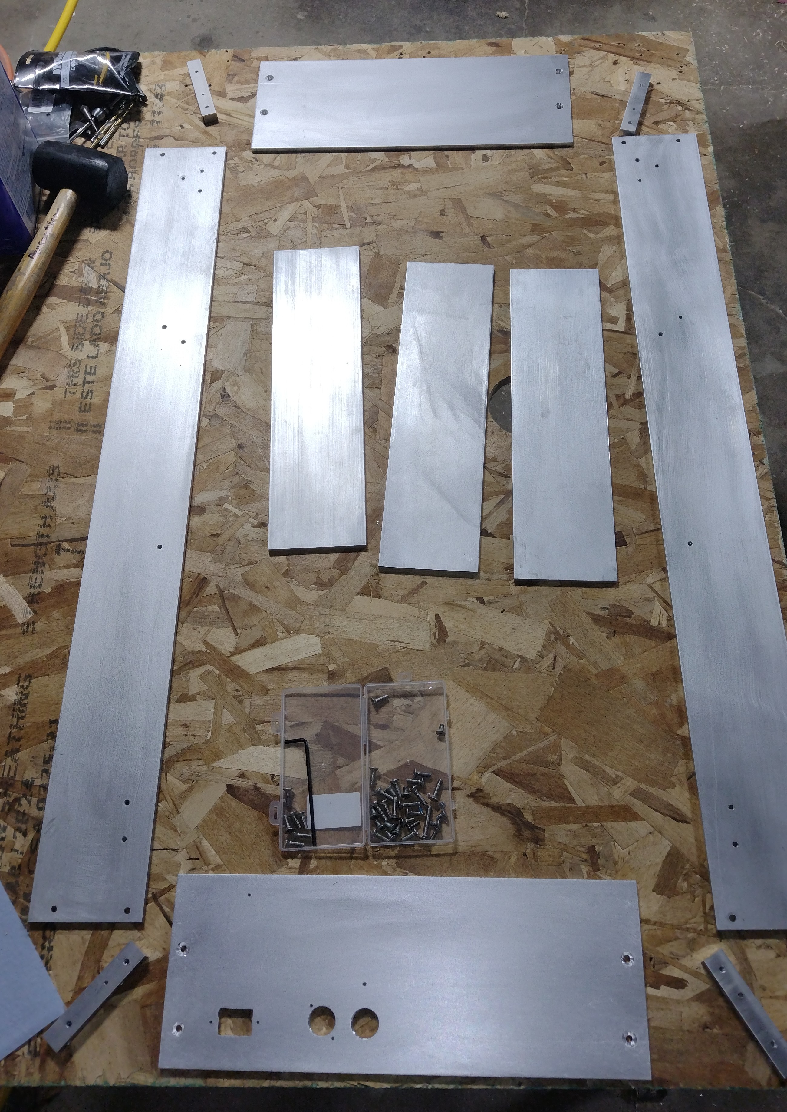
T6061 plate is plentiful, easy to work with, and reasonably sturdy. I didn't want to buy an off-the-shelf box because they are almost all intended to be used while closed, are too short, and I wanted an open frame. I've been tech'ing long enough to know that if I bought a prefab 4U box, the lid would just sit in a corner. Plus, I wanted the most depth I could get from my rack (about 3 feet). If this box is destined to be a twisted work of evolution and selective pressure, it might as well begin life with that anticipation.
I bought some heavy-duty rails and (with great annoyance and fanfare) adapted them to brackets to be fitted into a 19" rack.
TODO: pics, or it didn't happen.
There are two main power rails, 12V/5V. This box is huge, but only for ease of use and expansion. The actual power draw from this box isn't expected to exceed 40W. Ever.
TODO: pics, or it didn't happen.
Previous: Home IT Infrastructure
Next: Enginerding meme collection