Digitabulum: Flex circuits, and a release choice
2017-01-05 23:46 by Ian
After 1.5 years, the digit design is complete, and is real hardware on my desk. This was easily the hardest (and most expensive) part of the project.
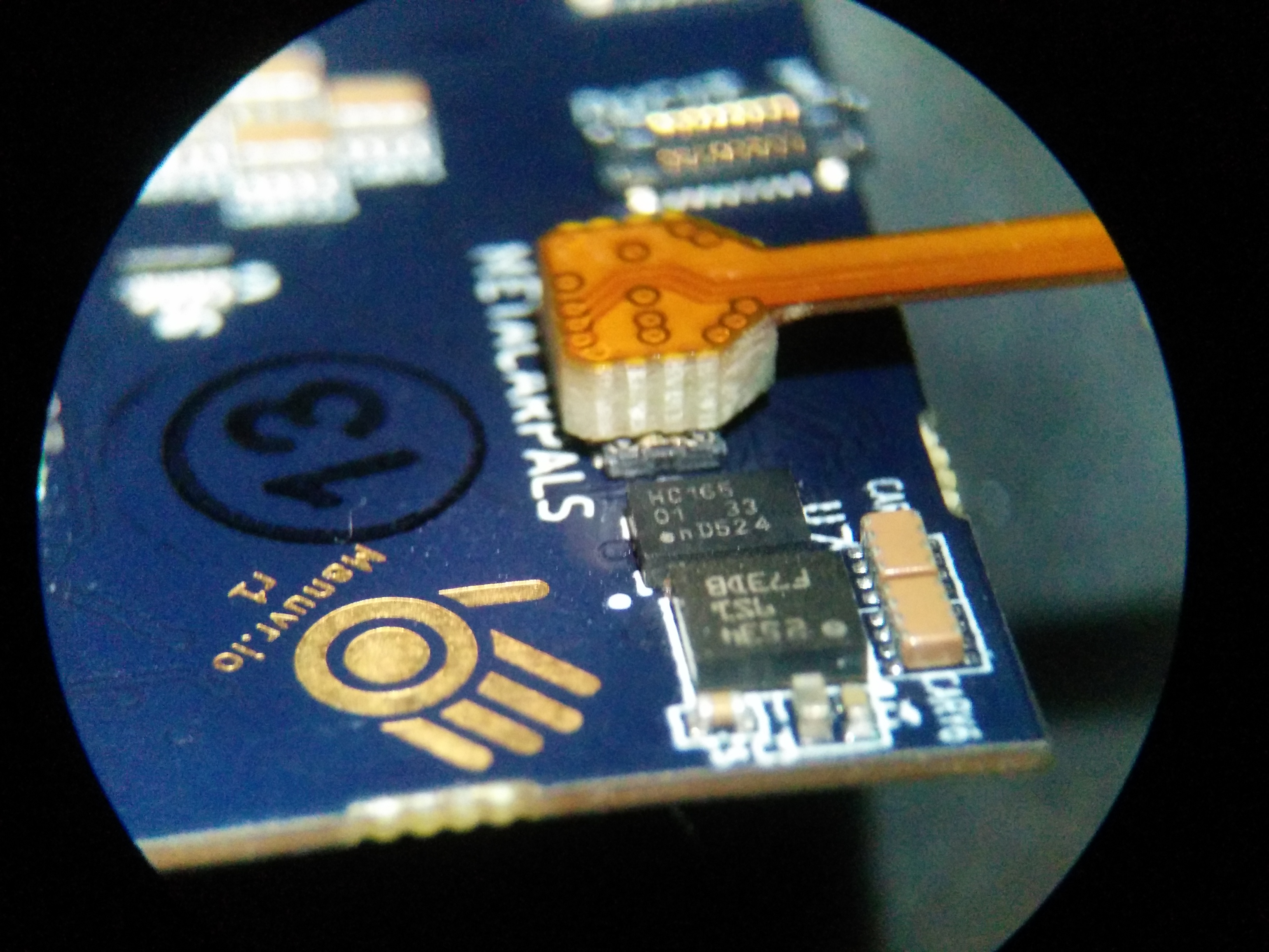
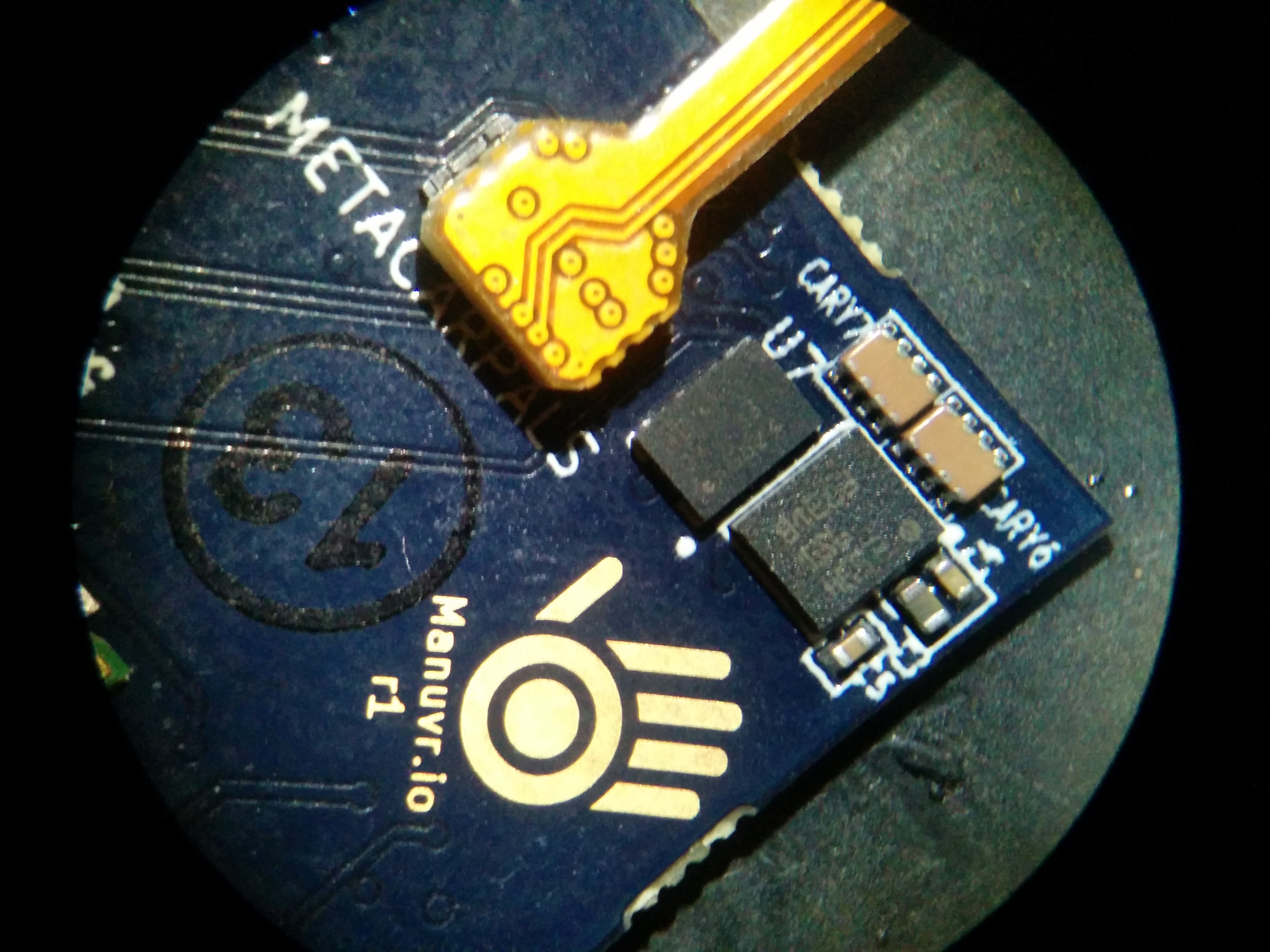
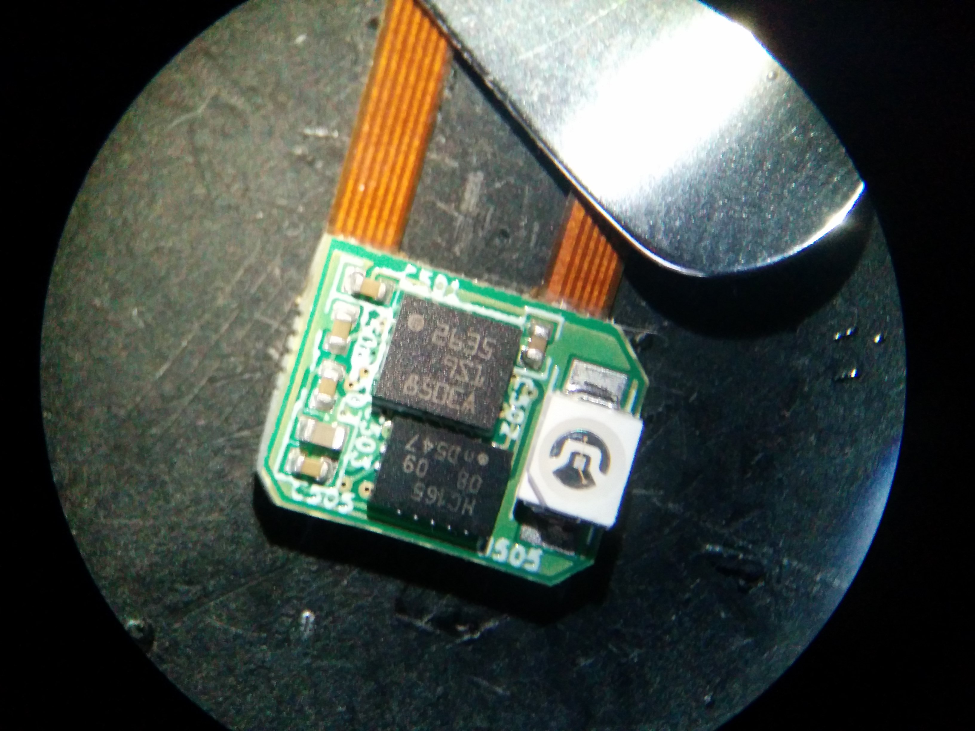
Flex circuits (metacarpals)
The metacarpals flex was the first to arrive. The digits themselves should arrive this weekend.
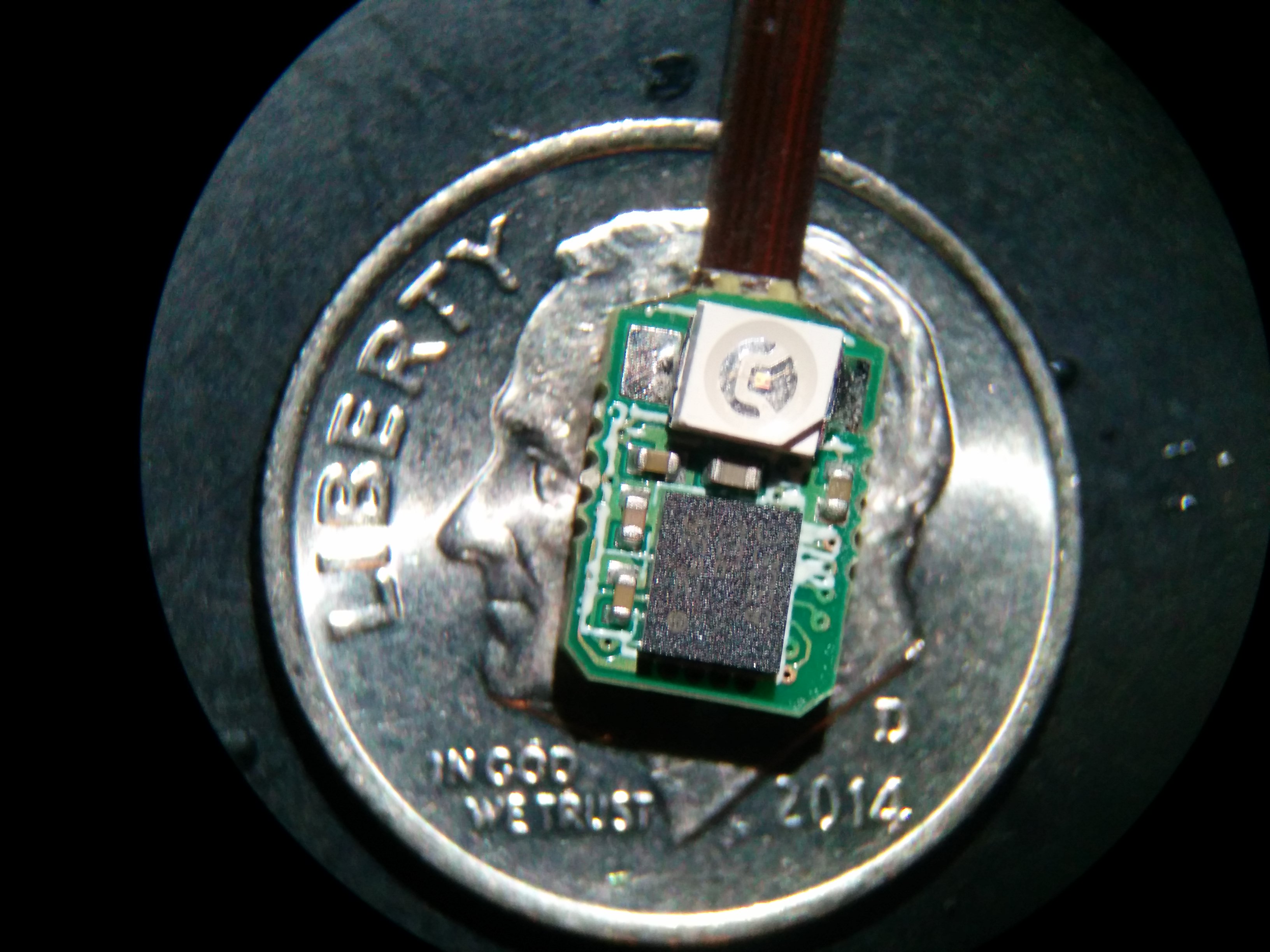
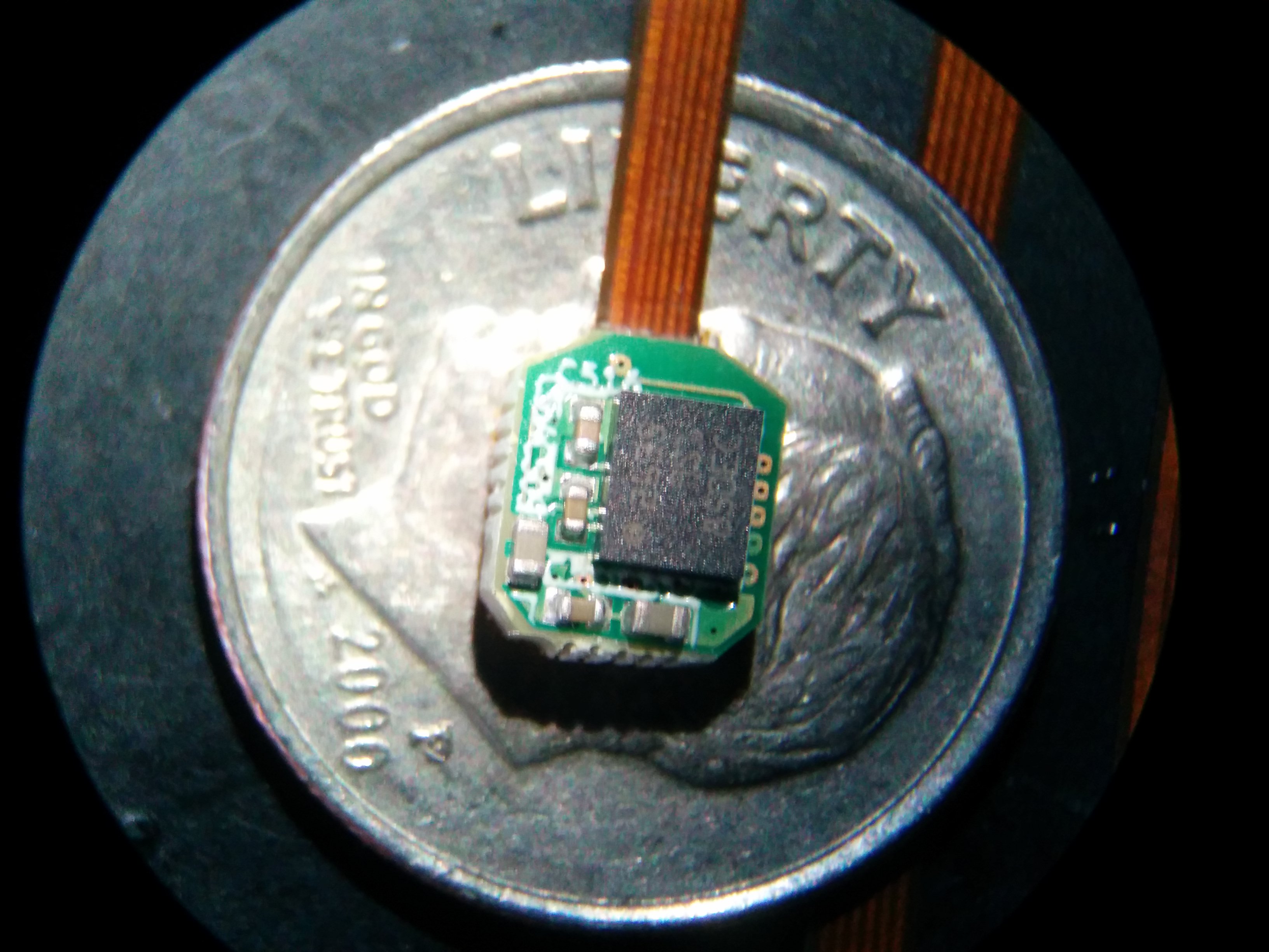
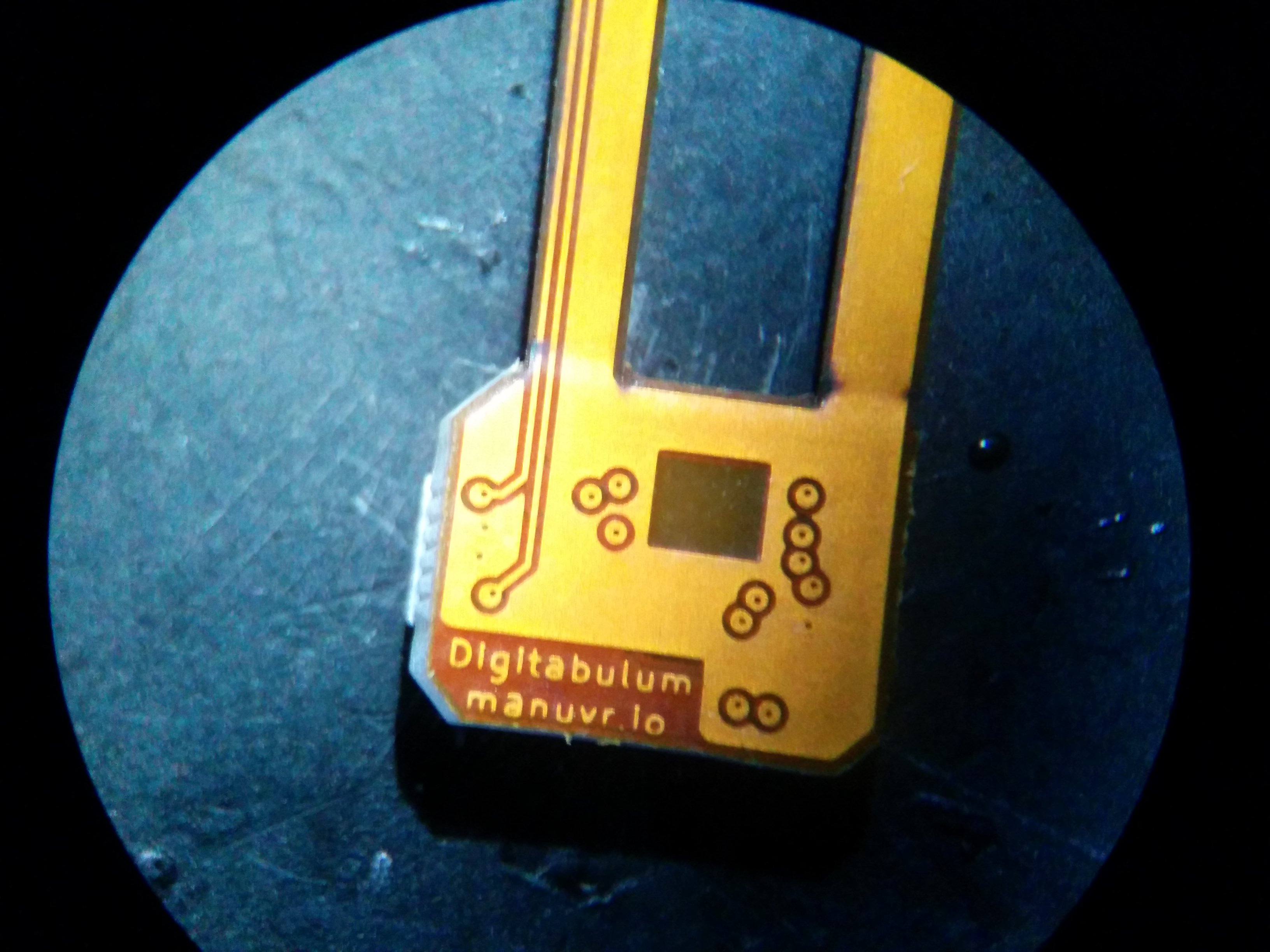
Metacarpals sensor node. This will be cast in a silicone nub the will sit at the dorsal surface of the hand.
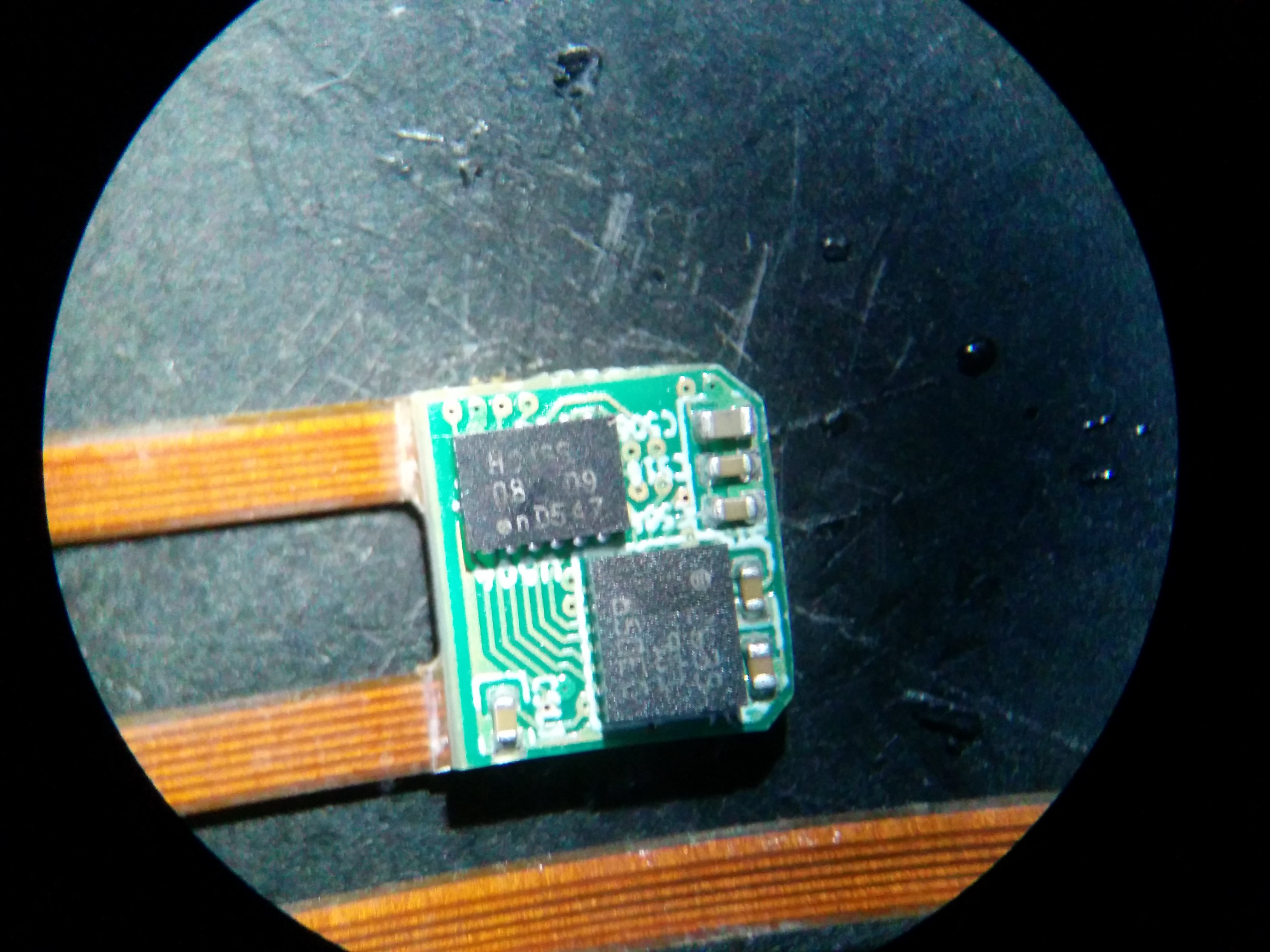
The connector side of the flex. The metacarpals flex has a slightly different pinout, because it only supports a single IMU, versus three for the digits.
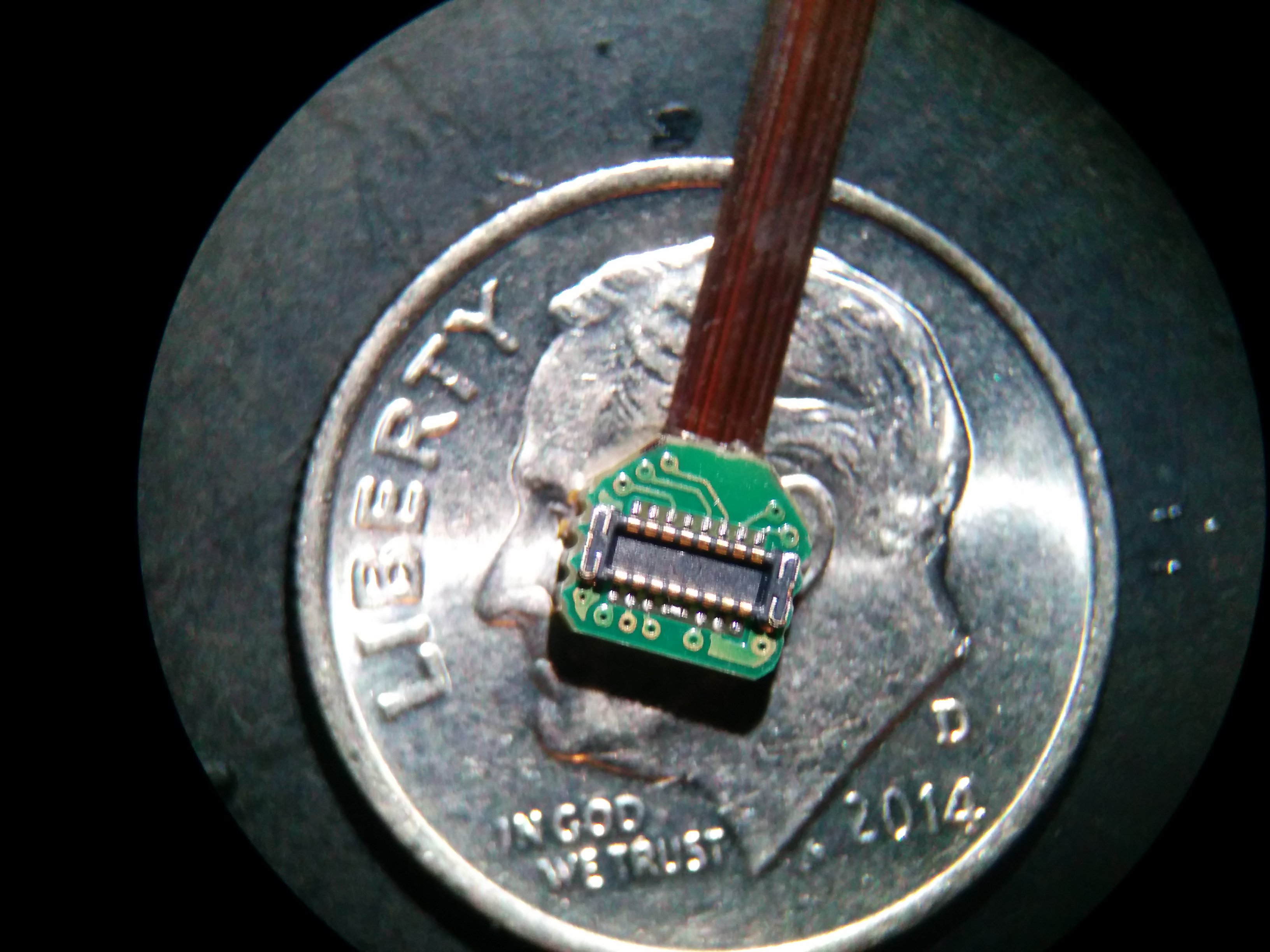
Fit is perfect. Although I feel that I left too much clearance between connectors. I have revised this in r2, and kept all digit connectors on the same side of the PCB.
When the digits arrive in a few days, I will post photos of the full apparatus, and dive back into discussing software.
As far as construction goes, there may be a few small changes to the digits prior to release (FR4 replaced by stiffener on the rear of the flex). But this will be more of a co$t decision than anything else. The design is substantially final (assuming I didn't make a mistake).
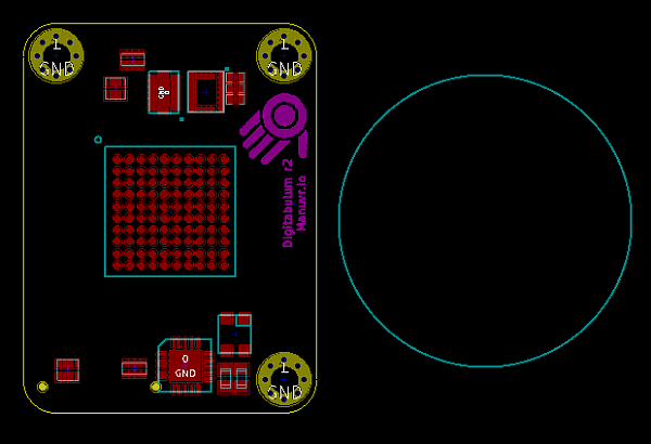
r2 initial release candidate design, and release options
TL;DR: The sensor front-end has been consolidated into a module a tad larger than a US quarter, and will be available on its own for use in other projects. Or you can buy a dev-kit ahead of a full product release.
The cyan circle on the right is the footprint of a US quarter.
Since I designed r2, the ESP32 happened, and I am currently evaluating its suitability for this application. It looks rosy for the ESP32. It has two cores, an FPU, more memory, has BT and WiFi, a thinner lithography process, and costs <$10 for an FCC certified module. Compared to r1's $20 MCU, $13 bluetooth module, and $5 of support circuitry that it would replace, the benefits are impossible to ignore. More on that choice in another post...
A few new sensors have come out since the shift to the LSM9DS1. Some of them even have orientation engines built-in. Some are more accurate. But none of them yet have the combination of bus, rate, accuracy, co$t, and size that makes the LSM9DS1 remain the cinch for this purpose.
To avoid needlessly re-designing the most complicated aspects of the project, I think I've found the happy level of modularity between r0's "replaceable resistors" versus r1's single PCB. The only features retained in the board shown above are the CPLD, the carpals IMU, and the LED driver. This is the minimum required part-count to support the sensor front-end and digit features (underside not shown).
Unlike r0 and r1 which ran at 3.3v fixed, r2 will be able to run from 3.3v down to 2.5v, in accordance with the preference of the rest of the system. The regulators, battery management, compute and comm will be located on the back-plane board, which can be cheaply iterated.
When the units are available, they will be so as...
A finished unit
This will be the last option available, but will be the "product" that non-hackers can buy and use with little-to-no technical work. There is no way for me to accurately posit a timeline.
A kit
If you are adventurous enough to assemble the unit and flash firmware, this is probably your best choice. Choose which parts of the finished unit you want, and assemble your own unit.
The menu will look something like this:
- Digitabulum board (sensor front-end)
- Digits and metacarpals (silicone-cast or bare)
- Choice of back-plane
- ESP32+PSU (the likely default)
- PSU back-plane (has PSU but no microcontroller)
- Breakout back-plane (For using your own microcontroller and PSU)
- Textile and casings
- Batteries
- (Optional) Addon development harness
Eventually, we hope to be in a position to offer validated third-party creations and community-developed addons
A sensor front-end and open-source driver to accelerate another project
I anticipate that someone will want to hook this up to an FPGA, TensorFlow, Pip-boy, industrial control bus, or a haptic apparatus of their own creation.
If you are that person, you can choose a breakout back-plane and supply your own microcontroller. If even that won't cut it you may take our open-source KiCAD template project for a back-plane and spec your own with whatever silicon you choose.
Hopefully, the digits arrive tomorrow from the fabricator. Saturday for sure. More to come.
---Ian
UPDATE 2017.01.07: Digits 1-5
The distal node
This had to be very thin, so as not to be wider than the nail of digit-5 ("pinkie").
The intermediate node
This node's shift register also handles the IRQ signals for the distal node,
The proximal node
Proximal contains the digit's LED so as to minimize the length of high-current traces near the magnetometers. As it stands, I am prepared for the possibility that I will need to de-rate this node's magnetometer readings while the LED is in operation. We'll find out if it becomes a problem,..
Since it isn't serving the IRQ signals for a second node, this shift register contains a hard-coded 4-bit value on the copper that allows the CPLD to do digit versioning and auto-discovery. Digit loss-of-contact will be reported as an interrupt within a few hundred microseconds of it having occurred.
And the rear of the proximal node
Note the window under the sensor's footprint. Every node has this design feature, and the KEEP-OUT window is on all six copper layers. The purpose is to avoid polluting the magnetometer environment with stray signals as much as possible for the given size. We also don't want to shield the sensor for impinging field shifts by converting them into ground-current eddies while the sensor is sweeping that long coil of flex circuit through Earth's field.
Magnetism is hard.
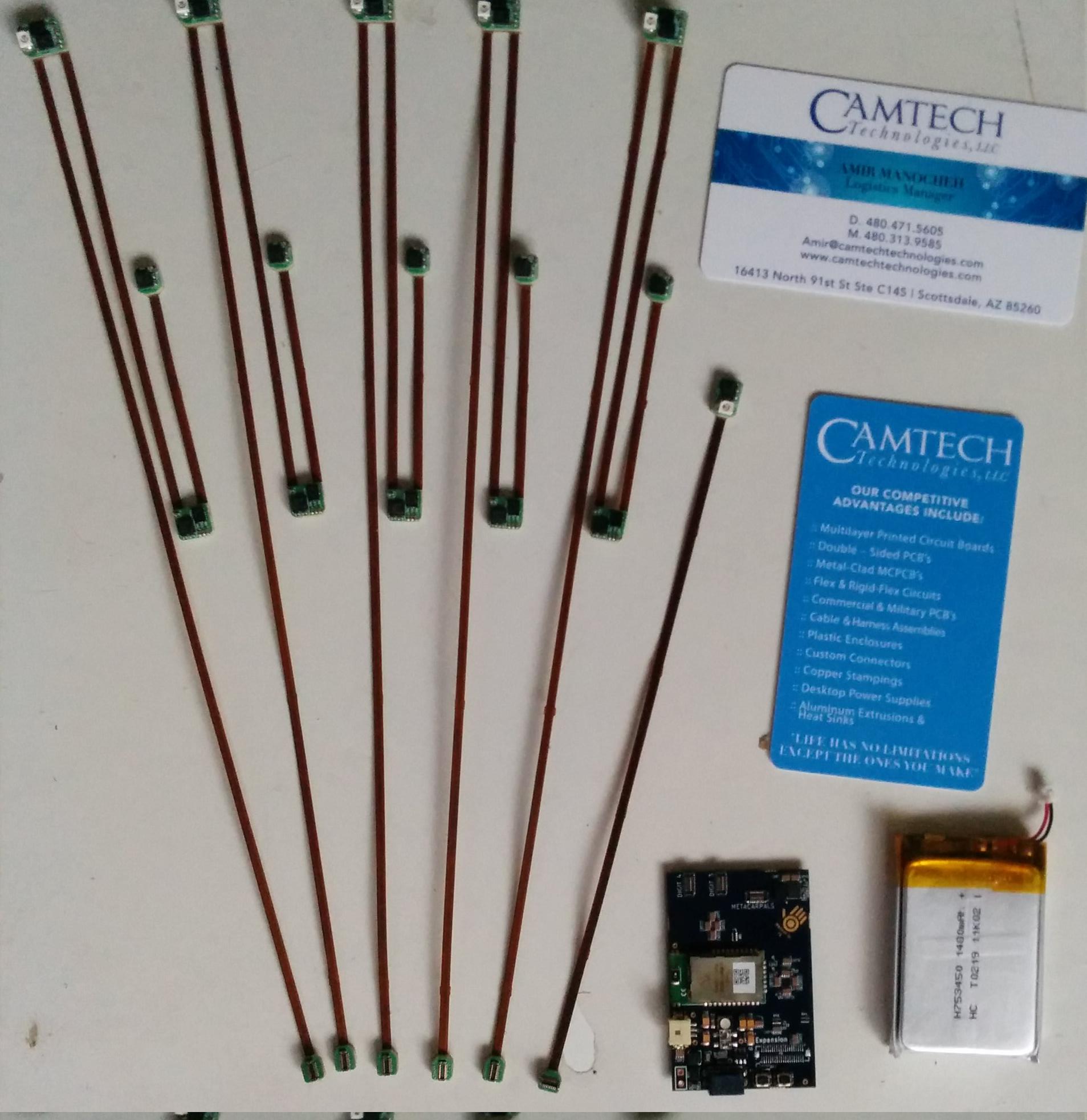
The complete set of hardware
My thanks go out to Camtech Technologies in Scottsdale, AZ for their excellent linkage of "intent" and "execution". They closely involved me in their process, and gave me the perspective that was necessary to build something this uncurbed. The parts look great, guys!
I will be putting the final touches on the release candidate PCBs in the coming week.
Previous: Digitabulum: Digit update
Next: Digitabulum r2 PCBs have arrived