Backup power notes
2025-06-21 01:00 by Ian
These are my notes on the battery backup system that I conjured for my house. My install is entirely custom, and self-owned.
When you live in a place that experiences heavy snowfall, power outages are basically assured. So I have installed 6kW of pure sinewave inverter capacity (configured as split-phase), 10kWh of battery backup, and 3kW of PV array. This has allowed me to keep the net online and the refrigerators cold, even if the power goes out for more than a day.
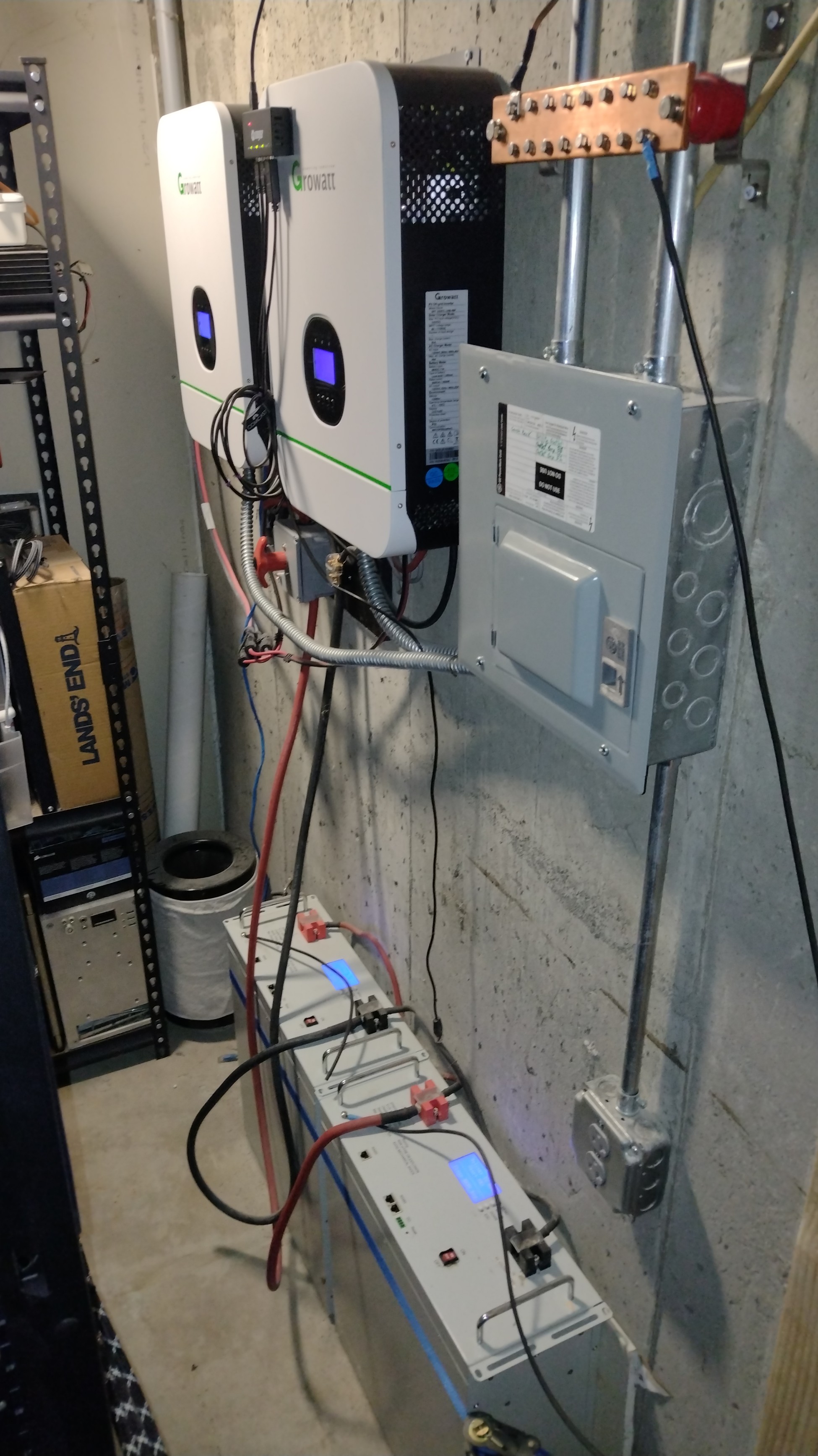
The inverters are a brace of Growatt 3000TL's configured for operation as split phase (240V). They are quite configurable, and also handle the power-point tracking for the PV array (entry via the conduit in the background), and keep the batteries (bottom of picture) topped up.
The batteries are a pair of ExpertPower EP48100's. They are (combined) 10kW hours of reserve using LiFePO4 chemistry. The inverters are configured to "micro-cycle" them so they don't ossify from being held at maximum charge for too long. ExpertPower did a fantastic job on these, and even gave me some source code (upon request) for the sake of evaluating and deploying them. So that company gets a grade "A" for hacker-friendliness and right-to-repair flavored concerns.
Below the inverters is a battery cut-off switch that is required to hard-restart the inverters after a full power loss. The batteries have their own internal management systems (BMS) that are conservative enough to balk when dumping their rated 100A into a load if the rise-time of the draw is too short. So this switch allows me to resistance-limit the inverter load to allow a manually-staged bring-up, should the inverters lose power completely.
The breaker box houses the breakers for the inverter output, and conceals the grid feed. My arrangement does not feed output back into the grid.
Most things in the house don't need battery backup. I can cook dinner by burning wood if I must, but I can't communicate with the outside world that way, nor keep food cold in the summer. So the critical circuits are:
- The refrigerators and freezers
- The comm rack
- The boiler control circuit (gas provides the heat, but the control elements are all electrical).
- A few side-circuits that give me the ability to add loads as-needed. Battery chargers, lights in a few key areas, and so forth.
The inverters and batteries all have RS-485 monitoring interfaces, and the inverters each have some basic control broken out via USB. So there is a USB hub magnetically stuck to the front of the foreground invert. It collects all that capability into a single USB cable that runs back to the comm rack. Presently, nothing is using the RS-485. The USB interface is mostly enough. Maybe some later day I will re-enable it.
Performance
With rationing and careful use, I have maintained the network for more than 24-hours of power outage during the Winter of 2023. At my latitude, the PV array is severely derated and doesn't outpace usage except for about 4 hours per day. I have not had occasion to test the inverter peak output, but the power quality I get from them is excellent. Their cut-over timing is phase-aware (you can't assume anything these days), and happens within a few wave-fronts.
TODO: When the grid is restored, the inverters will begin charging the batteries. A full recharge is done in a bit more than an hour, and heats the #000 gauge battery cables. There is a tremendous amount of power in those boxes. Although a fire would happen on the concrete floor, a class-D fire in this space would be a gift from the pit of Hell, and I should probably have a containment system before I add any additional capacity.
TODO: There have been outages that exceed my (reserves + generation), and necessitate a manual re-init to recover circuit operation. I need to write down the re-init checklist and post it on the machine, if not automate the problem away. If someone other than me needs to restore power, they would have difficulty.
TODO: Although this arrangement is located less than 2 meters from the primary breaker and has excellent mutual grounding, pedantry compels me to eventually add the neutral tie-point relay. The purpose being to avoid stray currents along the ground line, due to the neutral wire being tied to ground some distance (resistance) away.
TODO: The batteries could be stretched by powering certain elements of the comm rack via DC/DC conversion from the reserve's 48V. I have the gear for this, but doing it in a safe and tidy manner will take some thinking. I like having Ubiquiti's switch handle PoE, for instance. And I don't really want to hack their (otherwise flawless) work of art to add my own DC feed for PoE. But having it would shunt at least 100W off the inverters.
Previous: Home automation using HomeAssistant
Next: 2025.06.22: Beekeeping, year #3